How to Use DC MOTOR DRIVE: Examples, Pinouts, and Specs
Introduction
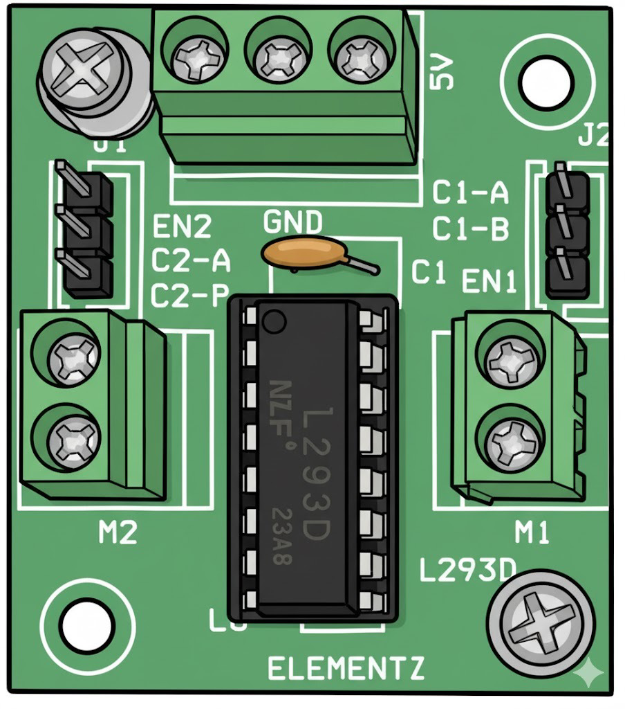
The L293D is a dual H-Bridge motor driver IC manufactured by H BRIGE. It is designed to control the speed, torque, and direction of DC motors by varying the voltage and current supplied to the motor. This component is widely used in robotics, automation systems, and other applications requiring precise motor control. The L293D can drive two DC motors simultaneously, making it a versatile choice for projects involving multiple motors.
Explore Projects Built with DC MOTOR DRIVE


Explore Projects Built with DC MOTOR DRIVE
Common Applications and Use Cases
- Robotics: Controlling wheels or robotic arms
- Conveyor belts in industrial automation
- Remote-controlled vehicles
- Home automation systems
- Small-scale CNC machines
Technical Specifications
The L293D is a robust and reliable motor driver IC with the following key specifications:
| Parameter | Value |
|---|---|
| Supply Voltage (Vcc1) | 4.5V to 36V |
| Logic Voltage (Vcc2) | 4.5V to 7V |
| Output Current (per channel) | 600mA (continuous), 1.2A (peak) |
| Number of Channels | 2 (dual H-Bridge) |
| Control Logic Levels | Low: 0V, High: 5V |
| Operating Temperature | -40°C to +150°C |
| Internal Diodes | Yes (for back EMF protection) |
Pin Configuration and Descriptions
The L293D IC comes in a 16-pin DIP (Dual Inline Package). Below is the pin configuration:
| Pin Number | Pin Name | Description |
|---|---|---|
| 1 | Enable 1,2 | Enables motor 1 (High = Enabled, Low = Disabled) |
| 2 | Input 1 | Logic input to control motor 1 direction (connected to microcontroller) |
| 3 | Output 1 | Output to motor 1 terminal |
| 4 | GND | Ground |
| 5 | GND | Ground |
| 6 | Output 2 | Output to motor 1 terminal |
| 7 | Input 2 | Logic input to control motor 1 direction (connected to microcontroller) |
| 8 | Vcc2 | Motor supply voltage (4.5V to 36V) |
| 9 | Enable 3,4 | Enables motor 2 (High = Enabled, Low = Disabled) |
| 10 | Input 3 | Logic input to control motor 2 direction (connected to microcontroller) |
| 11 | Output 3 | Output to motor 2 terminal |
| 12 | GND | Ground |
| 13 | GND | Ground |
| 14 | Output 4 | Output to motor 2 terminal |
| 15 | Input 4 | Logic input to control motor 2 direction (connected to microcontroller) |
| 16 | Vcc1 | Logic supply voltage (4.5V to 7V) |
Usage Instructions
How to Use the L293D in a Circuit
- Power Supply: Connect Vcc1 to a 5V logic supply and Vcc2 to the motor's supply voltage (4.5V to 36V). Ensure the ground (GND) pins are connected to the common ground of the circuit.
- Motor Connections: Connect the motor terminals to the Output pins (e.g., Output 1 and Output 2 for motor 1).
- Control Inputs: Use the Input pins (e.g., Input 1 and Input 2) to control the motor's direction. These pins are typically connected to a microcontroller or other control logic.
- Enable Pins: Set the Enable pins (e.g., Enable 1,2) to HIGH to activate the corresponding motor driver channel.
- Direction Control: Apply HIGH or LOW signals to the Input pins to control the motor's direction:
- Input 1 = HIGH, Input 2 = LOW: Motor rotates in one direction.
- Input 1 = LOW, Input 2 = HIGH: Motor rotates in the opposite direction.
- Both Inputs = LOW: Motor stops.
Important Considerations and Best Practices
- Heat Dissipation: The L293D can get hot during operation. Use a heat sink or ensure proper ventilation if driving motors at high currents.
- Back EMF Protection: The IC includes internal diodes for back EMF protection, but additional external diodes may be added for extra safety in high-power applications.
- Current Limitation: Do not exceed the maximum continuous current rating of 600mA per channel to avoid damaging the IC.
- Decoupling Capacitors: Place decoupling capacitors (e.g., 100µF and 0.1µF) near the Vcc pins to stabilize the power supply.
Example Code for Arduino UNO
Below is an example of how to control a DC motor using the L293D and an Arduino UNO:
// Define L293D pins connected to Arduino
const int enablePin = 9;  // Enable pin for motor 1
const int input1Pin = 7;  // Input 1 for motor 1
const int input2Pin = 8;  // Input 2 for motor 1

void setup() {
  // Set pin modes
  pinMode(enablePin, OUTPUT);
  pinMode(input1Pin, OUTPUT);
  pinMode(input2Pin, OUTPUT);

  // Initialize motor in stopped state
  digitalWrite(enablePin, LOW);  // Disable motor
  digitalWrite(input1Pin, LOW);  // Set input 1 to LOW
  digitalWrite(input2Pin, LOW);  // Set input 2 to LOW
}

void loop() {
  // Rotate motor in one direction
  digitalWrite(enablePin, HIGH);  // Enable motor
  digitalWrite(input1Pin, HIGH);  // Set input 1 to HIGH
  digitalWrite(input2Pin, LOW);   // Set input 2 to LOW
  delay(2000);                    // Run motor for 2 seconds

  // Stop motor
  digitalWrite(enablePin, LOW);   // Disable motor
  delay(1000);                    // Wait for 1 second

  // Rotate motor in the opposite direction
  digitalWrite(enablePin, HIGH);  // Enable motor
  digitalWrite(input1Pin, LOW);   // Set input 1 to LOW
  digitalWrite(input2Pin, HIGH);  // Set input 2 to HIGH
  delay(2000);                    // Run motor for 2 seconds

  // Stop motor
  digitalWrite(enablePin, LOW);   // Disable motor
  delay(1000);                    // Wait for 1 second
}
Troubleshooting and FAQs
Common Issues and Solutions
Motor Not Running:
- Ensure the Enable pin is set to HIGH.
- Verify the motor connections to the Output pins.
- Check the power supply voltage for both Vcc1 and Vcc2.
Motor Running in the Wrong Direction:
- Swap the HIGH/LOW signals on the Input pins.
- Verify the motor's polarity and connections.
Overheating:
- Reduce the motor's load or current draw.
- Add a heat sink to the L293D IC.
No Response from the IC:
- Check all connections, especially the ground.
- Ensure the logic voltage (Vcc1) is within the specified range (4.5V to 7V).
FAQs
Q: Can the L293D drive stepper motors?
A: Yes, the L293D can drive stepper motors by controlling the sequence of inputs to the H-Bridge channels.
Q: Can I use the L293D with a 3.3V microcontroller?
A: The L293D requires a minimum logic voltage of 4.5V. Use a level shifter or a 5V microcontroller for compatibility.
Q: How many motors can the L293D control?
A: The L293D can control up to two DC motors or one stepper motor.