
How to Use Surge Arrester LRS01-RS485 Lightning Protection: Examples, Pinouts, and Specs
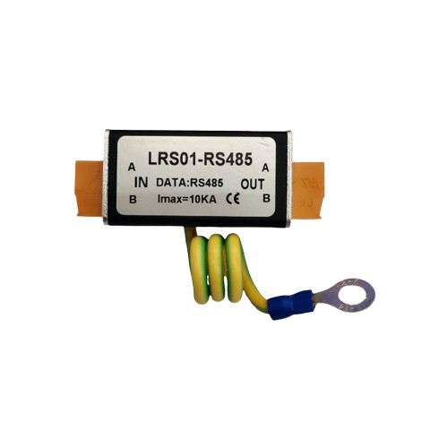
 Design with Surge Arrester LRS01-RS485 Lightning Protection in Cirkit Designer
Introduction
The LRS01-RS485 is a surge arrester designed to protect RS485 communication lines from voltage spikes caused by lightning strikes, power surges, or other transient events. Manufactured by Generic, this device ensures the safety and reliability of sensitive electronic equipment by clamping excessive voltages and diverting surge currents to the ground.
Explore Projects Built with Surge Arrester LRS01-RS485 Lightning Protection
 Open Project in Cirkit Designer
 Open Project in Cirkit Designer
 Open Project in Cirkit Designer
 Open Project in Cirkit Designer
Explore Projects Built with Surge Arrester LRS01-RS485 Lightning Protection
Open Project in Cirkit DesignerOpen Project in Cirkit DesignerOpen Project in Cirkit DesignerOpen Project in Cirkit DesignerCommon Applications and Use Cases
- Protection of RS485 communication networks in industrial automation systems.
- Safeguarding data transmission lines in building management systems (BMS).
- Lightning protection for outdoor RS485 devices such as sensors, controllers, and meters.
- Use in environments prone to electrical surges, such as factories, substations, and remote installations.
Technical Specifications
Key Technical Details
| Parameter | Value |
|---|---|
| Manufacturer Part ID | LRS01-RS485 |
| Nominal Operating Voltage | 5V to 12V (RS485 communication lines) |
| Maximum Surge Voltage | 6kV |
| Maximum Surge Current | 10kA |
| Clamping Voltage | 15V |
| Response Time | < 1ns |
| Operating Temperature Range | -40°C to +85°C |
| Storage Temperature Range | -40°C to +125°C |
| Dimensions | 60mm x 25mm x 20mm |
| Mounting Type | DIN rail or inline installation |
Pin Configuration and Descriptions
The LRS01-RS485 has four connection terminals for easy integration into RS485 communication lines.
| Terminal Label | Description |
|---|---|
| A | RS485 Data Line A (positive differential line) |
| B | RS485 Data Line B (negative differential line) |
| GND | Ground connection for surge current diversion |
| PE | Protective Earth for additional grounding |
Usage Instructions
How to Use the Component in a Circuit
- Identify the RS485 Communication Lines: Locate the A and B data lines in your RS485 network.
- Connect the Surge Arrester:
- Connect the A terminal of the LRS01-RS485 to the RS485 Data Line A.
- Connect the B terminal of the LRS01-RS485 to the RS485 Data Line B.
- Connect the GND terminal to the ground of your system.
- Optionally, connect the PE terminal to a dedicated protective earth for enhanced grounding.
- Mount the Device: Secure the LRS01-RS485 on a DIN rail or inline with the communication lines.
- Verify Connections: Ensure all connections are secure and properly insulated to prevent accidental short circuits.
Important Considerations and Best Practices
- Grounding: Proper grounding is critical for effective surge protection. Ensure the GND and PE terminals are connected to a low-impedance ground.
- Placement: Install the surge arrester as close as possible to the equipment being protected to minimize the length of unprotected wiring.
- Environmental Conditions: Ensure the device is installed in an environment within its operating temperature range (-40°C to +85°C).
- Periodic Inspection: Regularly inspect the device for signs of wear or damage, especially after a surge event.
Arduino UNO Integration Example
While the LRS01-RS485 is not directly connected to an Arduino UNO, it can be used to protect RS485 communication modules interfaced with the Arduino. Below is an example of how to use the LRS01-RS485 in an RS485 communication setup.
Example Code for RS485 Communication
#include <SoftwareSerial.h>

// Define RS485 communication pins
#define RX_PIN 10  // Arduino pin connected to RS485 module's RO (Receive Out)
#define TX_PIN 11  // Arduino pin connected to RS485 module's DI (Data In)
#define DE_PIN 12  // Arduino pin connected to RS485 module's DE (Driver Enable)
#define RE_PIN 13  // Arduino pin connected to RS485 module's RE (Receiver Enable)

SoftwareSerial RS485Serial(RX_PIN, TX_PIN);

void setup() {
  pinMode(DE_PIN, OUTPUT);
  pinMode(RE_PIN, OUTPUT);

  // Initialize RS485 communication
  RS485Serial.begin(9600);

  // Set RS485 module to receive mode
  digitalWrite(DE_PIN, LOW);
  digitalWrite(RE_PIN, LOW);

  Serial.begin(9600);
  Serial.println("RS485 Communication Initialized");
}

void loop() {
  // Example: Send data over RS485
  digitalWrite(DE_PIN, HIGH); // Enable driver
  digitalWrite(RE_PIN, HIGH); // Disable receiver
  RS485Serial.println("Hello from Arduino!");
  delay(1000);

  // Example: Receive data over RS485
  digitalWrite(DE_PIN, LOW); // Disable driver
  digitalWrite(RE_PIN, LOW); // Enable receiver
  if (RS485Serial.available()) {
    String receivedData = RS485Serial.readString();
    Serial.print("Received: ");
    Serial.println(receivedData);
  }
}
Troubleshooting and FAQs
Common Issues Users Might Face
No Protection During a Surge Event:
- Cause: Improper grounding or loose connections.
- Solution: Verify that the GND and PE terminals are securely connected to a low-impedance ground.
RS485 Communication Failure:
- Cause: Incorrect wiring of the A and B terminals.
- Solution: Double-check the polarity of the RS485 data lines and ensure A is connected to A, and B is connected to B.
Device Overheating:
- Cause: Continuous exposure to high surge currents or operation outside the specified temperature range.
- Solution: Inspect the device for damage and ensure it is installed in a suitable environment.
Physical Damage After a Surge Event:
- Cause: Surge current exceeded the device's maximum rating.
- Solution: Replace the device and consider additional surge protection measures upstream.
Solutions and Tips for Troubleshooting
- Use a multimeter to check continuity and proper grounding of the GND and PE terminals.
- Test the RS485 communication lines with and without the surge arrester to isolate potential issues.
- If the device frequently fails, evaluate the surge environment and consider upgrading to a higher-rated surge protection device.