How to Use BUCK CONVERTER: Examples, Pinouts, and Specs
Introduction
A buck converter is a type of DC-DC converter that steps down voltage while stepping up current. It achieves this by using a switching element (typically a transistor), an inductor, a diode, and a capacitor. Buck converters are highly efficient and are widely used in applications where a stable, lower voltage is required from a higher input voltage source.
Explore Projects Built with BUCK CONVERTER


Explore Projects Built with BUCK CONVERTER
Common Applications and Use Cases
- Powering microcontrollers and low-voltage devices from higher voltage sources
- Battery-powered systems to regulate voltage levels
- Voltage regulation in renewable energy systems (e.g., solar panels)
- Automotive electronics for stepping down 12V to lower voltages
- LED drivers and portable electronic devices
Technical Specifications
Below are the general technical specifications for a typical buck converter. Note that actual values may vary depending on the specific model.
Key Technical Details
- Input Voltage Range: 4.5V to 40V (varies by model)
- Output Voltage Range: Adjustable (e.g., 1.25V to 37V)
- Output Current: Up to 3A (or higher for advanced models)
- Efficiency: Up to 95% (depending on load and input/output conditions)
- Switching Frequency: 150 kHz to 1 MHz (varies by design)
- Thermal Protection: Built-in in many models
- Short-Circuit Protection: Available in most designs
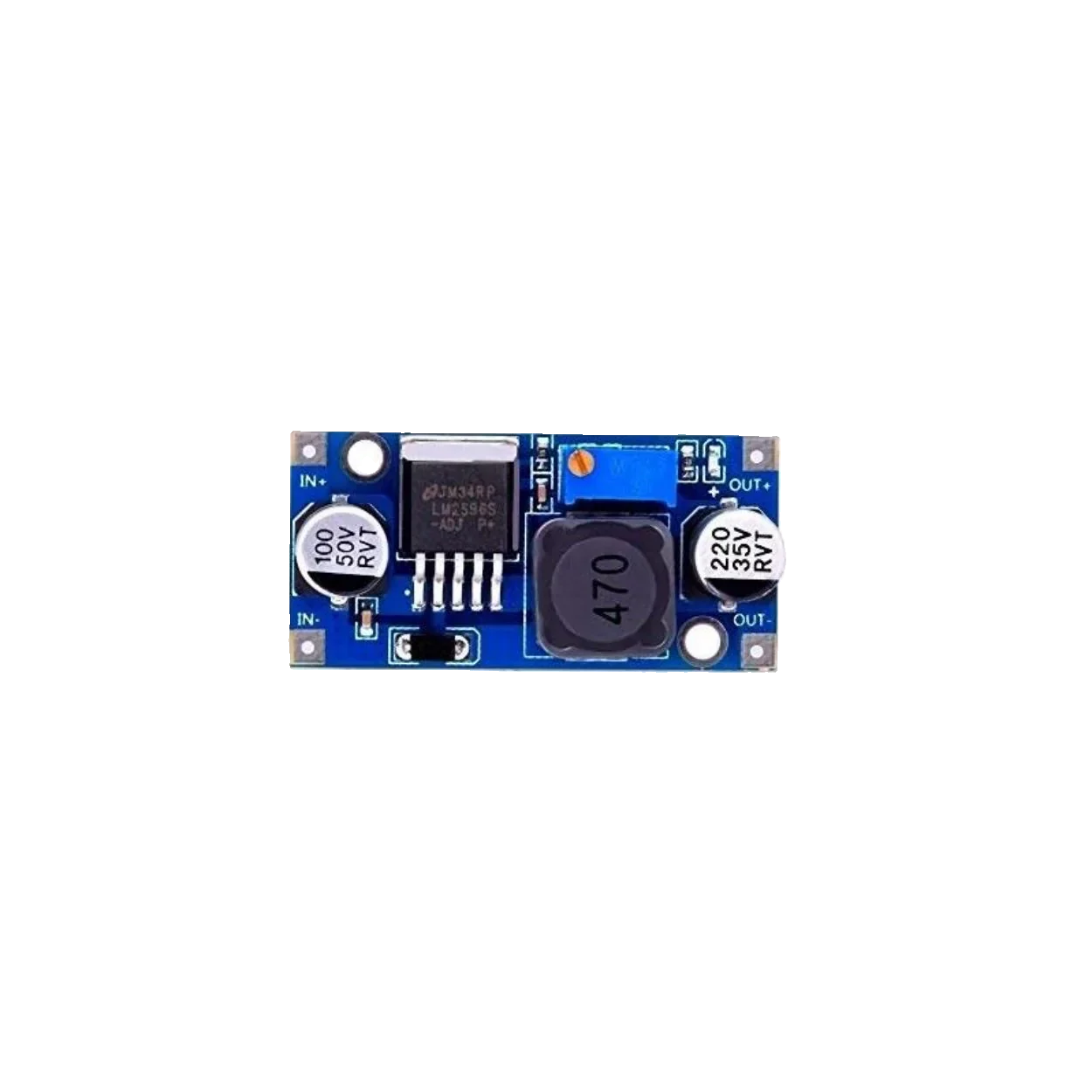
Pin Configuration and Descriptions
The pinout of a buck converter module (e.g., LM2596-based module) is as follows:
| Pin Name | Description |
|---|---|
| VIN | Input voltage pin. Connect the higher voltage source here. |
| GND | Ground pin. Connect to the ground of the circuit. |
| VOUT | Output voltage pin. Provides the stepped-down voltage. |
| ADJ (optional) | Adjustment pin for setting the output voltage (used in adjustable models). |
Usage Instructions
How to Use the Component in a Circuit
- Connect the Input Voltage:
- Attach the positive terminal of the input voltage source to the
VINpin. - Connect the negative terminal of the input source to the
GNDpin.
- Attach the positive terminal of the input voltage source to the
- Connect the Load:
- Attach the positive terminal of the load to the
VOUTpin. - Connect the negative terminal of the load to the
GNDpin.
- Attach the positive terminal of the load to the
- Adjust the Output Voltage (if applicable):
- For adjustable buck converters, use the onboard potentiometer to set the desired output voltage.
- Measure the output voltage using a multimeter while adjusting the potentiometer.
- Power On:
- Turn on the input voltage source and verify the output voltage and current.
Important Considerations and Best Practices
- Input Voltage: Ensure the input voltage is within the specified range of the buck converter.
- Output Voltage: Do not exceed the rated output voltage or current of the module.
- Heat Dissipation: For high-power applications, ensure proper heat dissipation using heatsinks or fans.
- Capacitor Selection: Use low-ESR capacitors for better performance and stability.
- Inductor Selection: Ensure the inductor value matches the design requirements for your load.
- Filtering: Add input and output capacitors to reduce noise and improve stability.
Example: Using a Buck Converter with Arduino UNO
Below is an example of using a buck converter to power an Arduino UNO from a 12V source:
- Connect the 12V source to the
VINandGNDpins of the buck converter. - Adjust the output voltage to 5V using the potentiometer.
- Connect the
VOUTpin of the buck converter to the5Vpin of the Arduino UNO. - Connect the
GNDpin of the buck converter to theGNDpin of the Arduino UNO.
// Example Arduino code to blink an LED powered by a buck converter
// Ensure the buck converter is set to 5V output before connecting to Arduino

const int ledPin = 13; // Pin connected to the onboard LED

void setup() {
  pinMode(ledPin, OUTPUT); // Set the LED pin as an output
}

void loop() {
  digitalWrite(ledPin, HIGH); // Turn the LED on
  delay(1000);                // Wait for 1 second
  digitalWrite(ledPin, LOW);  // Turn the LED off
  delay(1000);                // Wait for 1 second
}
Troubleshooting and FAQs
Common Issues and Solutions
No Output Voltage:
- Check the input voltage and ensure it is within the specified range.
- Verify all connections, especially
VINandGND. - Ensure the potentiometer is not set to the minimum output voltage.
Overheating:
- Ensure the load does not exceed the rated current of the buck converter.
- Add a heatsink or fan to improve heat dissipation.
Output Voltage Fluctuations:
- Check the input voltage stability.
- Add input and output capacitors to reduce noise.
- Verify the inductor and capacitor values are appropriate for the load.
Low Efficiency:
- Ensure the input voltage is not too close to the output voltage.
- Use low-ESR capacitors and high-quality components.
FAQs
Q: Can I use a buck converter to power sensitive electronics?
A: Yes, but ensure the output voltage is stable and noise-free. Adding filtering capacitors can help.
Q: What happens if I exceed the input voltage range?
A: Exceeding the input voltage range can damage the buck converter. Always stay within the specified range.
Q: Can I use a buck converter to step up voltage?
A: No, a buck converter is designed only to step down voltage. For stepping up voltage, use a boost converter.
Q: How do I calculate the required inductor value?
A: The inductor value depends on the input voltage, output voltage, switching frequency, and load current. Refer to the datasheet of the specific buck converter IC for detailed calculations.