How to Use CPU_kit: Examples, Pinouts, and Specs
Introduction
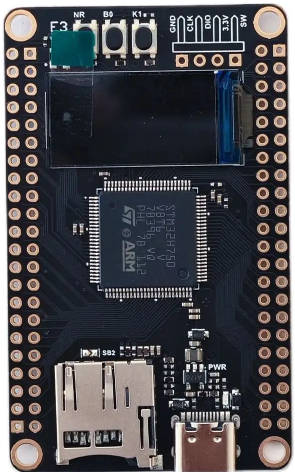
The STM CPU Kit (Part ID: CPU) is a comprehensive package designed to provide users with the essential components required for building or upgrading a computer system. At its core is the central processing unit (CPU), which serves as the brain of the computer, executing instructions and processing data. The kit typically includes a CPU, a compatible heatsink, a cooling fan, and, in some cases, a motherboard. This all-in-one solution simplifies the process of assembling a functional computing system.
Explore Projects Built with CPU_kit


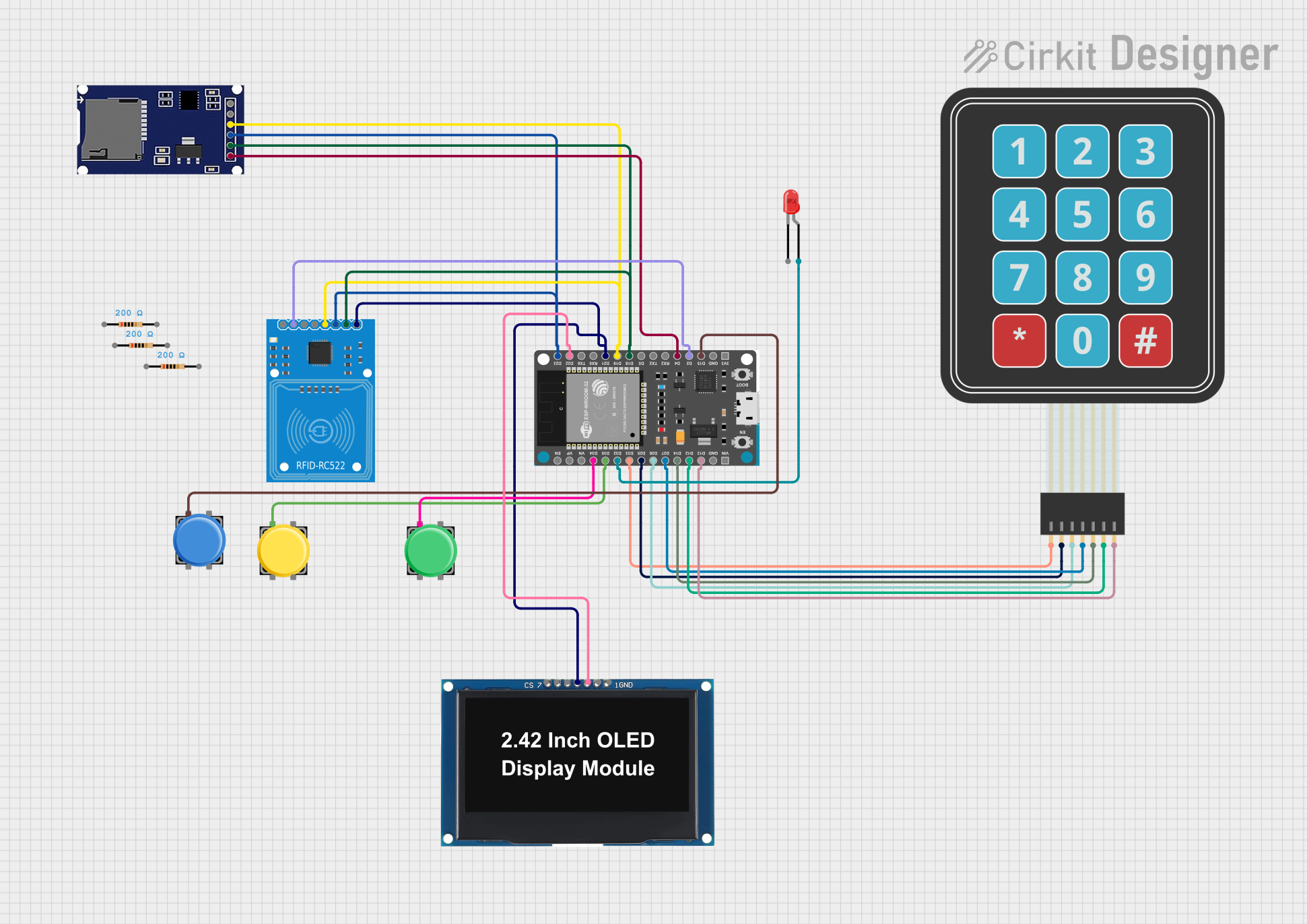
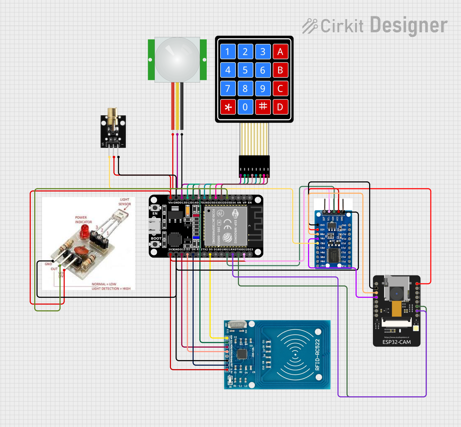
Explore Projects Built with CPU_kit
Common Applications and Use Cases
- Personal Computers (PCs): Ideal for building custom desktops or upgrading existing systems.
- Workstations: Suitable for high-performance tasks such as video editing, 3D rendering, and software development.
- Embedded Systems: Can be used in industrial or IoT applications requiring robust processing power.
- Gaming Systems: Provides the processing power needed for modern gaming applications.
Technical Specifications
Key Technical Details
| Parameter | Specification |
|---|---|
| Manufacturer | STM |
| Part ID | CPU |
| CPU Architecture | x86 or ARM (varies by model) |
| Clock Speed | 2.0 GHz to 5.0 GHz (model-dependent) |
| Number of Cores | 4 to 16 (model-dependent) |
| Thermal Design Power (TDP) | 65W to 125W |
| Cooling Solution | Heatsink and fan included |
| Socket Compatibility | LGA1200, AM4, or other (varies) |
| Memory Support | DDR4 or DDR5 (model-dependent) |
| Integrated Graphics | Optional (varies by model) |
Pin Configuration and Descriptions
The CPU itself is designed to fit into a specific socket on the motherboard. Below is a general description of the pin configuration for an LGA (Land Grid Array) socket:
| Pin Type | Description |
|---|---|
| Power Pins | Supply power to the CPU |
| Ground Pins | Provide grounding for the CPU |
| Data Pins | Facilitate communication with memory and I/O |
| Control Pins | Manage CPU operations and system control |
| Clock Pins | Synchronize CPU operations |
Note: The exact pin configuration depends on the CPU model and socket type. Refer to the motherboard's documentation for detailed pinout information.
Usage Instructions
How to Use the CPU Kit in a System
Prepare the Workspace:
- Ensure you are working in an anti-static environment to prevent damage to the components.
- Gather all necessary tools, such as a screwdriver and thermal paste (if not pre-applied).
Install the CPU:
- Open the CPU socket latch on the motherboard.
- Align the CPU with the socket using the alignment markers (e.g., a triangle or notch).
- Gently place the CPU into the socket and secure the latch.
Apply Thermal Paste (if required):
- If the heatsink does not have pre-applied thermal paste, apply a small amount (pea-sized) to the center of the CPU.
Attach the Heatsink and Fan:
- Place the heatsink on top of the CPU, ensuring proper alignment.
- Secure the heatsink using the provided mounting mechanism.
- Connect the fan's power cable to the appropriate header on the motherboard (usually labeled "CPU_FAN").
Connect Additional Components:
- Install memory (RAM), storage devices, and other peripherals as needed.
- Connect the power supply to the motherboard and other components.
Power On and Test:
- Power on the system and enter the BIOS/UEFI to verify that the CPU is recognized and operating correctly.
- Monitor temperatures to ensure proper cooling.
Important Considerations and Best Practices
- Compatibility: Ensure the CPU is compatible with the motherboard's socket and chipset.
- Cooling: Proper cooling is essential to prevent overheating and ensure optimal performance.
- BIOS Updates: Some motherboards may require a BIOS update to support newer CPUs.
- Static Precautions: Always use an anti-static wrist strap or mat when handling the CPU and other sensitive components.
Example: Using the CPU Kit with an Arduino UNO
While the CPU kit is not directly compatible with an Arduino UNO, it can be used in conjunction with a computer to program and interface with the Arduino. Below is an example of Arduino code that can be uploaded using a computer built with the CPU kit:
// Blink an LED connected to pin 13 of the Arduino UNO
// This code demonstrates basic functionality for testing the Arduino setup.

void setup() {
  pinMode(13, OUTPUT); // Set pin 13 as an output
}

void loop() {
  digitalWrite(13, HIGH); // Turn the LED on
  delay(1000);            // Wait for 1 second
  digitalWrite(13, LOW);  // Turn the LED off
  delay(1000);            // Wait for 1 second
}
Troubleshooting and FAQs
Common Issues and Solutions
CPU Not Recognized by Motherboard:
- Solution: Check for socket compatibility and ensure the CPU is properly seated. Update the motherboard BIOS if necessary.
System Overheating:
- Solution: Verify that the heatsink and fan are securely attached. Reapply thermal paste if needed. Ensure proper airflow in the case.
No Display Output:
- Solution: If the CPU does not have integrated graphics, ensure a discrete GPU is installed. Check all power and video connections.
System Fails to Boot:
- Solution: Double-check all connections, including power supply cables. Remove and reseat the RAM and CPU.
FAQs
Q: Can I use this CPU kit with any motherboard?
A: No, the CPU must be compatible with the motherboard's socket and chipset. Refer to the motherboard's specifications for compatibility.Q: How often should I replace the thermal paste?
A: It is recommended to replace the thermal paste every 2-3 years or whenever the CPU is removed.Q: Does the kit include a pre-installed cooling solution?
A: Most STM CPU kits include a heatsink and fan with pre-applied thermal paste, but this may vary by model.Q: Can I overclock the CPU included in this kit?
A: Overclocking depends on the specific CPU model and motherboard support. Ensure proper cooling and follow manufacturer guidelines.
This documentation provides a comprehensive guide to using the STM CPU Kit effectively. For further assistance, consult the manufacturer's support resources.