
How to Use Encoder KY-040: Examples, Pinouts, and Specs
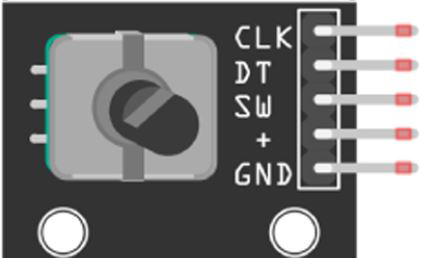
 Design with Encoder KY-040 in Cirkit Designer
Introduction
The KY-040 is a rotary encoder that converts the angular position or rotation of a shaft into digital signals. Unlike potentiometers, rotary encoders can rotate infinitely in either direction without limits. The KY-040 also includes a built-in push-button switch, making it a versatile component for user input. It is commonly used in applications such as volume control, menu navigation, motor control, and other interactive systems.
Explore Projects Built with Encoder KY-040
 Open Project in Cirkit Designer
 Open Project in Cirkit Designer
 Open Project in Cirkit Designer
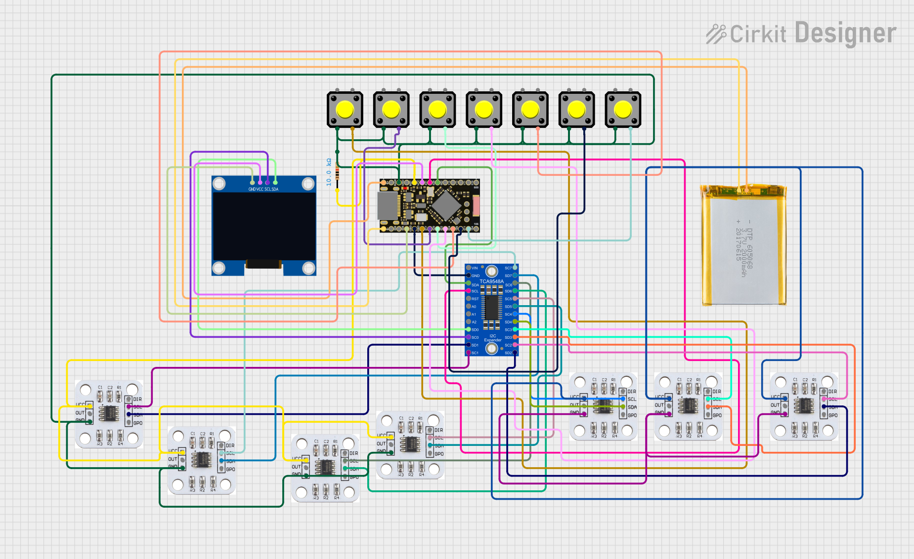 Open Project in Cirkit Designer
Explore Projects Built with Encoder KY-040
Open Project in Cirkit DesignerOpen Project in Cirkit DesignerOpen Project in Cirkit DesignerOpen Project in Cirkit DesignerCommon Applications:
- Volume and brightness adjustment
- Menu selection in embedded systems
- Motor speed and position control
- Robotics and automation systems
- DIY electronics projects
Technical Specifications
The KY-040 rotary encoder has the following key specifications:
| Parameter | Value |
|---|---|
| Operating Voltage | 3.3V - 5V |
| Output Type | Digital (Quadrature Signals) |
| Number of Pulses | 20 Pulses per Revolution |
| Push-Button Switch | Integrated |
| Dimensions | 19mm x 15mm x 29mm |
Pin Configuration and Descriptions
The KY-040 module has 5 pins, as described in the table below:
| Pin | Label | Description |
|---|---|---|
| 1 | GND | Ground connection for the module. |
| 2 | + | Power supply pin (3.3V or 5V). |
| 3 | SW | Push-button switch output. Active LOW when the button is pressed. |
| 4 | DT | Data signal (Channel B) for the rotary encoder. |
| 5 | CLK | Clock signal (Channel A) for the rotary encoder. |
Usage Instructions
How to Use the KY-040 in a Circuit
- Power the Module: Connect the
+pin to a 3.3V or 5V power source and theGNDpin to ground. - Connect the Encoder Outputs:
- Connect the
CLK(Channel A) andDT(Channel B) pins to digital input pins on your microcontroller. - These pins generate quadrature signals that indicate the direction and speed of rotation.
- Connect the
- Use the Push-Button:
- Connect the
SWpin to a digital input pin on your microcontroller. - The button is active LOW, so it will output
0when pressed and1when released.
- Connect the
- Read the Signals:
- Monitor the
CLKandDTsignals to determine the direction and number of steps rotated. - Use the
SWsignal to detect button presses.
- Monitor the
Important Considerations and Best Practices
- Debouncing: The mechanical nature of the encoder may cause signal noise or "bouncing." Use software debouncing or external capacitors to filter out noise.
- Pull-Up Resistors: If your microcontroller does not have internal pull-up resistors, add external pull-up resistors to the
SW,CLK, andDTpins. - Power Supply: Ensure the module is powered within its operating voltage range (3.3V - 5V) to avoid damage.
Example Code for Arduino UNO
Below is an example Arduino sketch to read the KY-040 rotary encoder and detect button presses:
// Define pin connections for the KY-040
#define CLK 2  // Clock pin (Channel A)
#define DT 3   // Data pin (Channel B)
#define SW 4   // Switch pin

int lastCLKState;  // To store the previous state of the CLK pin
int currentCLKState;  // To store the current state of the CLK pin
int counter = 0;  // Counter to track encoder position

void setup() {
  pinMode(CLK, INPUT);  // Set CLK pin as input
  pinMode(DT, INPUT);   // Set DT pin as input
  pinMode(SW, INPUT_PULLUP);  // Set SW pin as input with pull-up resistor

  Serial.begin(9600);  // Initialize serial communication
  lastCLKState = digitalRead(CLK);  // Read the initial state of the CLK pin
}

void loop() {
  // Read the current state of the CLK pin
  currentCLKState = digitalRead(CLK);

  // Check if the CLK state has changed
  if (currentCLKState != lastCLKState) {
    // Determine the direction of rotation
    if (digitalRead(DT) != currentCLKState) {
      counter++;  // Clockwise rotation
    } else {
      counter--;  // Counterclockwise rotation
    }

    // Print the counter value to the Serial Monitor
    Serial.print("Position: ");
    Serial.println(counter);
  }

  // Update the last CLK state
  lastCLKState = currentCLKState;

  // Check if the button is pressed
  if (digitalRead(SW) == LOW) {
    Serial.println("Button Pressed!");
    delay(200);  // Debounce delay
  }
}
Key Notes for the Code:
- The
CLKandDTpins are used to detect rotation direction and steps. - The
SWpin is used to detect button presses. - A debounce delay is added to avoid multiple detections of a single button press.
Troubleshooting and FAQs
Common Issues and Solutions
No Response from the Encoder:
- Ensure the module is powered correctly (3.3V or 5V).
- Verify all connections are secure and match the pin configuration.
Incorrect or Erratic Readings:
- Add software debouncing to filter out noise from the encoder signals.
- Check for loose connections or faulty wiring.
Button Not Detected:
- Ensure the
SWpin is connected to a digital input pin with a pull-up resistor. - Verify the button is not physically damaged.
- Ensure the
Direction Detection is Reversed:
- Swap the connections of the
CLKandDTpins to correct the direction.
- Swap the connections of the
FAQs
Q: Can the KY-040 be used with 3.3V microcontrollers like ESP32?
A: Yes, the KY-040 operates at both 3.3V and 5V, making it compatible with 3.3V microcontrollers.
Q: How many steps does the encoder have per revolution?
A: The KY-040 has 20 pulses per revolution, but the actual steps may vary depending on your implementation.
Q: Do I need external pull-up resistors?
A: If your microcontroller does not have internal pull-up resistors, you will need to add external ones to the SW, CLK, and DT pins.
Q: Can I use the KY-040 for precise angle measurement?
A: The KY-040 is not designed for high-precision angle measurement. It is better suited for user input and general-purpose applications.
By following this documentation, you can effectively integrate the KY-040 rotary encoder into your projects!