
How to Use SparkFun Stepoko: Examples, Pinouts, and Specs
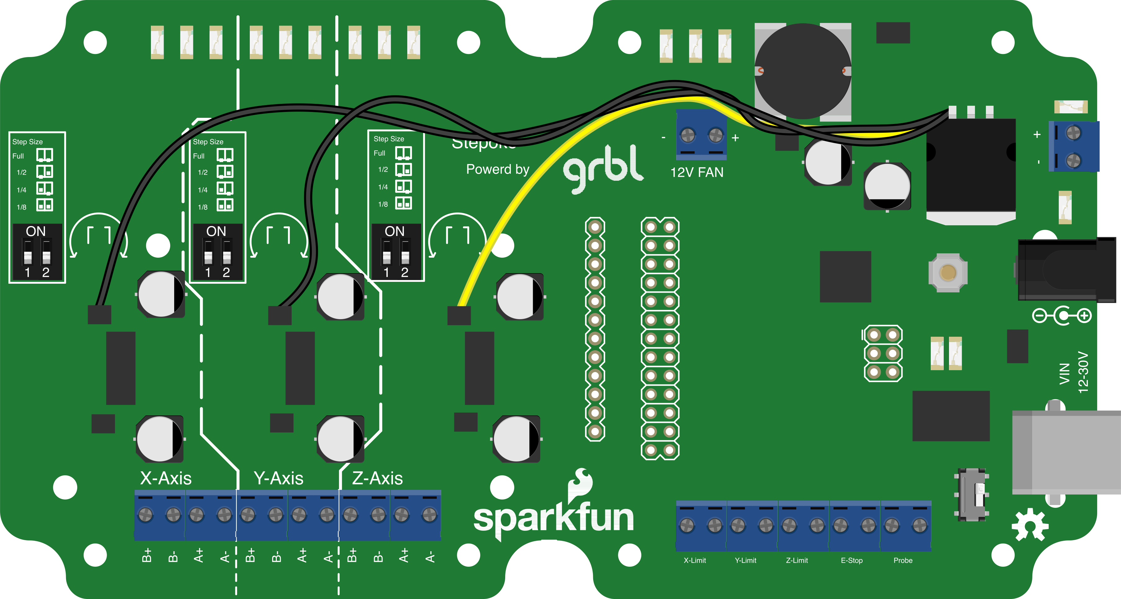
 Design with SparkFun Stepoko in Cirkit Designer
Introduction
The SparkFun Stepoko is a compact, open-source stepper motor driver board designed for controlling stepper motors in CNC (Computer Numerical Control) applications. Manufactured by SparkFun Electronics, the Stepoko integrates an Arduino-compatible microcontroller, making it highly versatile and customizable for a wide range of projects. It supports multiple stepper motor configurations and is ideal for applications requiring precise motor control, such as 3D printers, laser cutters, and CNC milling machines.
Explore Projects Built with SparkFun Stepoko
 Open Project in Cirkit Designer
 Open Project in Cirkit Designer
 Open Project in Cirkit Designer
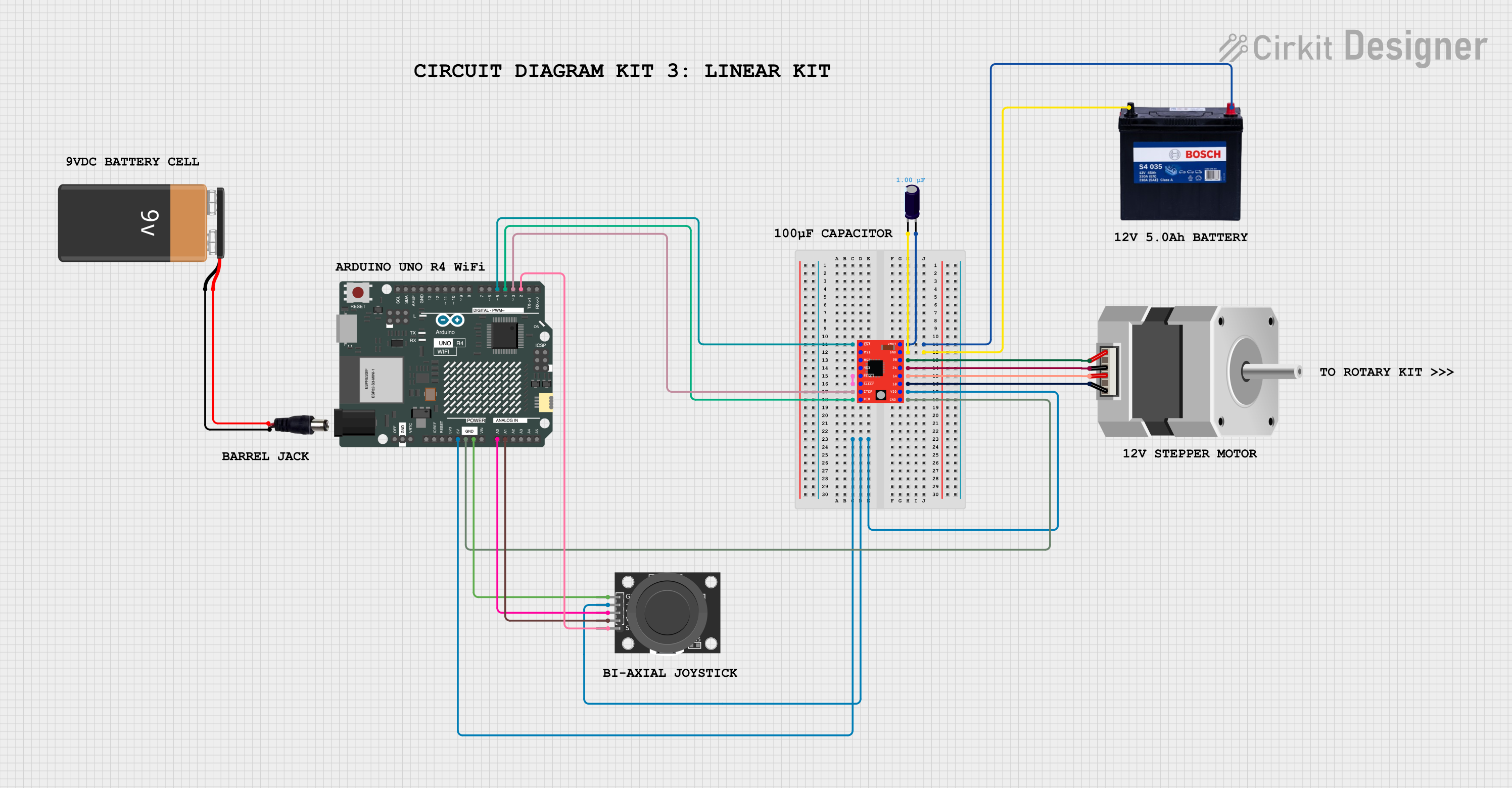 Open Project in Cirkit Designer
Explore Projects Built with SparkFun Stepoko
Open Project in Cirkit DesignerOpen Project in Cirkit DesignerOpen Project in Cirkit DesignerOpen Project in Cirkit DesignerCommon Applications
- CNC machines for milling, engraving, and cutting
- 3D printers
- Laser cutters and engravers
- Robotics and automation systems
- DIY motion control projects
Technical Specifications
The SparkFun Stepoko is built to provide reliable and efficient stepper motor control. Below are its key technical details:
Key Specifications
| Parameter | Value |
|---|---|
| Microcontroller | ATmega328P (Arduino-compatible) |
| Input Voltage Range | 12V to 30V DC |
| Stepper Motor Driver ICs | DRV8811 (Texas Instruments) |
| Maximum Motor Current | 2.5A per phase |
| Microstepping Modes | Full, 1/2, 1/4, 1/8, 1/16 |
| Communication Interface | USB (via FTDI FT231X) |
| Supported Software | GRBL (preloaded) |
| Dimensions | 4.0" x 3.0" (101.6mm x 76.2mm) |
| Mounting Holes | Standard CNC shield mounting pattern |
Pin Configuration and Descriptions
The Stepoko board features several connectors and pins for interfacing with stepper motors, power supplies, and external devices. Below is a detailed description of its pin configuration:
Motor Connections
| Pin Label | Description |
|---|---|
| X+, X- | Connectors for the X-axis stepper motor |
| Y+, Y- | Connectors for the Y-axis stepper motor |
| Z+, Z- | Connectors for the Z-axis stepper motor |
Power and Control
| Pin Label | Description |
|---|---|
| VIN | Main power input (12V to 30V DC) |
| GND | Ground connection |
| USB | USB interface for programming and control |
Limit Switches
| Pin Label | Description |
|---|---|
| X-LIMIT | Input for X-axis limit switch |
| Y-LIMIT | Input for Y-axis limit switch |
| Z-LIMIT | Input for Z-axis limit switch |
Additional Pins
| Pin Label | Description |
|---|---|
| A4, A5 | I2C communication pins |
| RX, TX | Serial communication pins |
Usage Instructions
The SparkFun Stepoko is designed to be user-friendly and easy to integrate into CNC and motion control systems. Follow the steps below to get started:
Step 1: Powering the Board
- Connect a DC power supply (12V to 30V) to the VIN and GND terminals.
- Ensure the power supply can provide sufficient current for your stepper motors.
Step 2: Connecting Stepper Motors
- Connect the stepper motors to the X+, X-, Y+, Y-, Z+, and Z- terminals.
- Verify the wiring matches the motor's datasheet to avoid incorrect connections.
Step 3: Programming the Board
- Connect the Stepoko to your computer using a USB cable.
- Install the Arduino IDE and ensure the correct drivers for the FTDI FT231X are installed.
- Select "Arduino Uno" as the board type in the Arduino IDE.
- Use GRBL-compatible software (e.g., Universal Gcode Sender) to upload G-code files and control the board.
Step 4: Configuring Limit Switches
- Connect limit switches to the X-LIMIT, Y-LIMIT, and Z-LIMIT pins.
- Configure the GRBL settings to enable and define the behavior of the limit switches.
Example Code for Arduino
Below is an example of how to send basic commands to the Stepoko using the Arduino IDE:
// Example: Sending G-code commands to the Stepoko via Serial
void setup() {
  Serial.begin(115200); // Initialize serial communication at 115200 baud
  delay(1000);          // Wait for the Stepoko to initialize

  // Send a sample G-code command to move the X-axis
  Serial.println("G0 X10"); // Move X-axis to position 10
}

void loop() {
  // No additional code needed for this example
}
Best Practices
- Always double-check motor wiring to prevent damage to the board or motors.
- Use a power supply with sufficient current capacity to handle all connected motors.
- Ensure proper cooling and ventilation for the board during operation.
Troubleshooting and FAQs
Common Issues and Solutions
Issue: Motors are not moving.
- Solution: Verify the motor wiring and ensure the power supply is connected and providing the correct voltage.
Issue: Limit switches are not functioning.
- Solution: Check the wiring of the limit switches and ensure they are enabled in the GRBL settings.
Issue: USB connection is not recognized.
- Solution: Install the correct FTDI drivers and ensure the USB cable is functional.
Issue: Motors are skipping steps or stalling.
- Solution: Reduce the feed rate or acceleration settings in the GRBL configuration.
FAQs
Can I use the Stepoko with other software besides GRBL?
- The Stepoko is optimized for GRBL, but you can reprogram the ATmega328P for other applications if needed.
What types of stepper motors are compatible with the Stepoko?
- The Stepoko supports bipolar stepper motors with a maximum current of 2.5A per phase.
Is the Stepoko open-source?
- Yes, the Stepoko is fully open-source, and its design files and firmware are available on the SparkFun website.
By following this documentation, you can effectively use the SparkFun Stepoko for your CNC and motion control projects.