How to Use Multimeter: Examples, Pinouts, and Specs
Introduction
A multimeter is an electronic measuring instrument that combines several measurement functions in one unit. It is a versatile tool capable of measuring voltage (both AC and DC), current, and resistance. Some advanced multimeters also include features for testing continuity, diodes, capacitance, and frequency. Multimeters are essential tools for electricians, engineers, and hobbyists, and they are widely used for troubleshooting electrical and electronic circuits.
Explore Projects Built with Multimeter
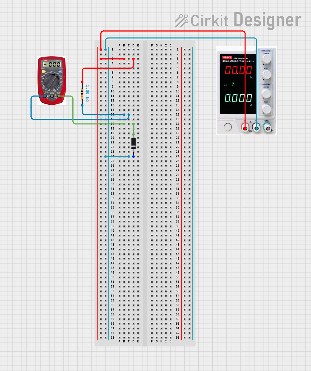
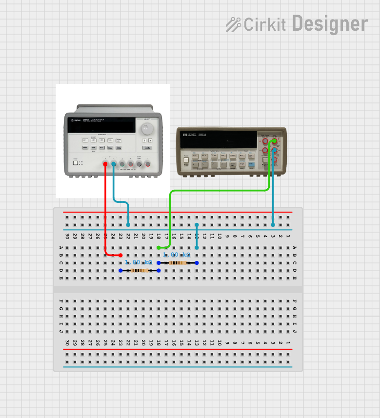
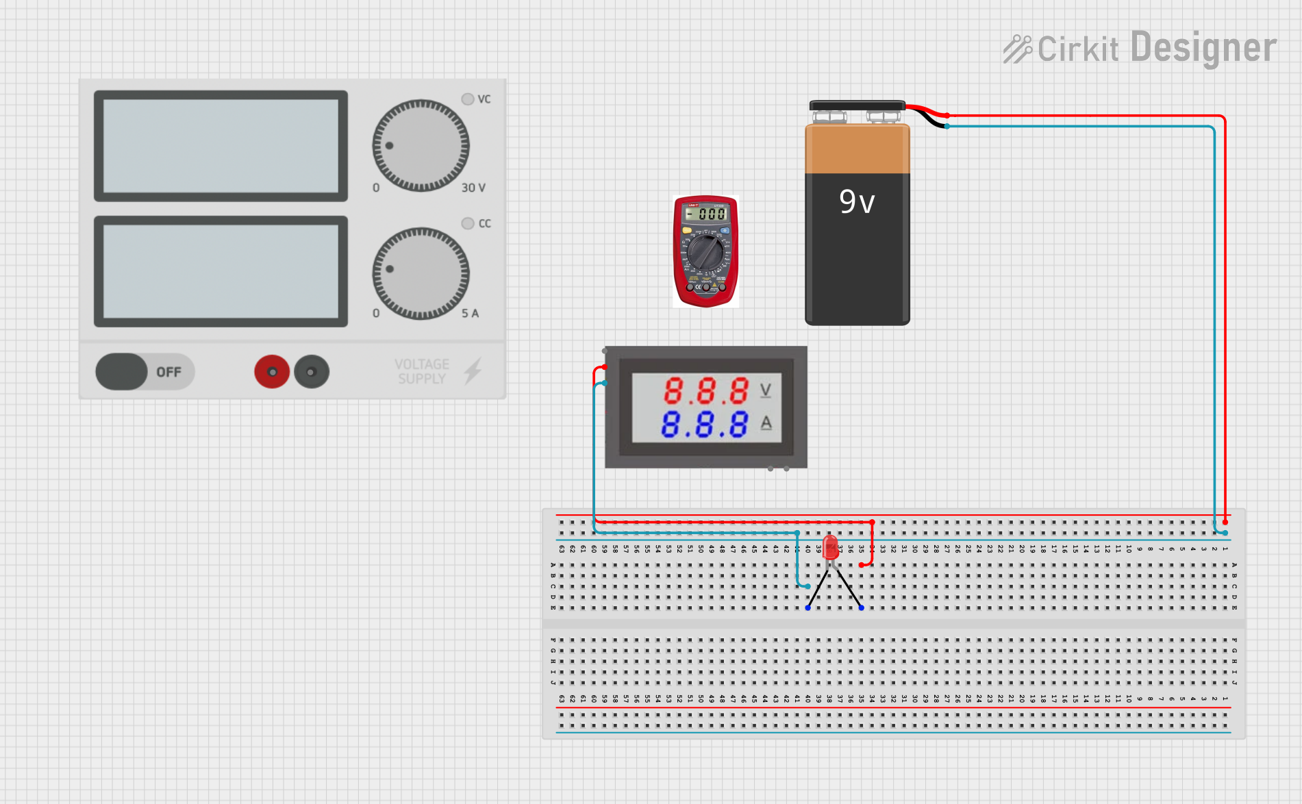
Explore Projects Built with Multimeter
Common Applications and Use Cases
- Measuring DC and AC voltage in circuits
- Checking current flow in electrical systems
- Testing the resistance of components like resistors
- Verifying circuit continuity
- Diagnosing faults in electrical appliances and devices
- Testing diodes and transistors in electronic circuits
Technical Specifications
The specifications of a multimeter can vary depending on the model and manufacturer. Below are the general technical details for a typical digital multimeter:
| Parameter | Specification |
|---|---|
| Voltage Measurement | DC: 0-1000V, AC: 0-750V |
| Current Measurement | DC: 0-10A, AC: 0-10A |
| Resistance Measurement | 0-40MΩ |
| Display Type | Digital (LCD) or Analog |
| Accuracy | ±(0.5% to 2.0%) depending on the range and model |
| Continuity Test | Audible buzzer for resistance < 50Ω |
| Power Supply | 9V battery (commonly used in digital multimeters) |
| Input Impedance | Typically 10MΩ |
| Safety Rating | CAT II / CAT III / CAT IV (varies by model) |
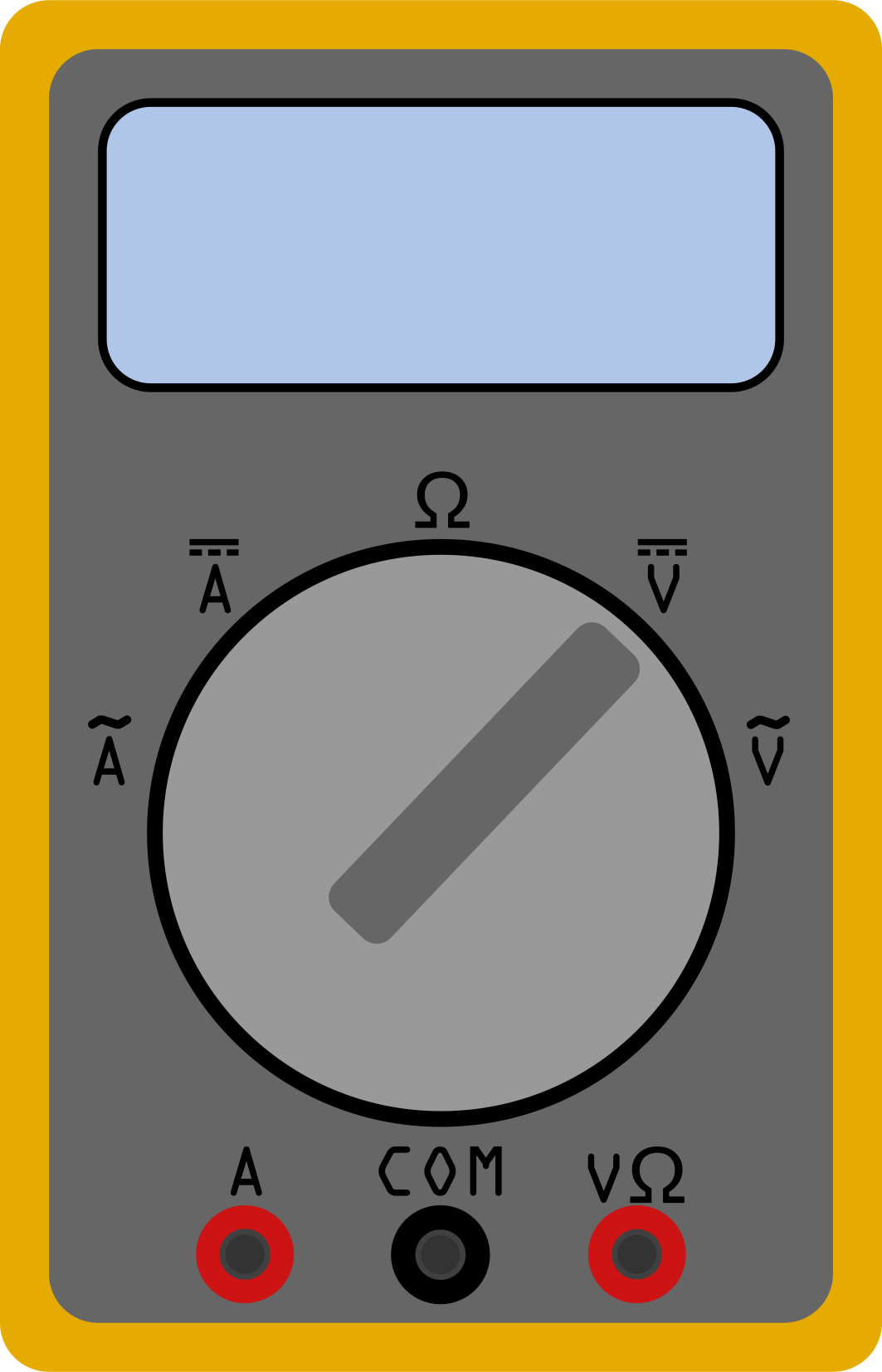
Common Multimeter Ports and Functions
| Port/Function | Description |
|---|---|
| COM (Common) | Ground or reference connection for measurements |
| V/Ω/mA Port | Used for voltage, resistance, and low current |
| 10A Port | Dedicated port for high current measurements |
| Rotary Dial | Selects the measurement type and range |
| Hold Button | Freezes the current reading on the display |
| Backlight Button | Activates the display backlight (if available) |
Usage Instructions
How to Use the Multimeter in a Circuit
Voltage Measurement:
- Set the rotary dial to the appropriate DC or AC voltage range.
- Connect the black probe to the COM port and the red probe to the V/Ω/mA port.
- Place the probes across the component or circuit where voltage needs to be measured.
- Read the voltage value on the display.
Current Measurement:
- Set the rotary dial to the appropriate current range (DC or AC).
- For currents below 200mA, use the V/Ω/mA port; for higher currents, use the 10A port.
- Break the circuit and connect the multimeter in series with the load.
- Read the current value on the display.
Resistance Measurement:
- Set the rotary dial to the resistance (Ω) range.
- Ensure the circuit is powered off to avoid damage to the multimeter.
- Connect the probes across the component to measure its resistance.
- Read the resistance value on the display.
Continuity Test:
- Set the rotary dial to the continuity test mode (often marked with a diode symbol).
- Connect the probes across the circuit or component.
- If the circuit is continuous, the multimeter will emit a beep.
Important Considerations and Best Practices
- Always start with the highest range when unsure of the measurement value.
- Never measure resistance in a live circuit.
- Use the correct port for current measurements to avoid damaging the multimeter.
- Replace the battery promptly when the low battery indicator appears.
- Observe the safety rating of the multimeter and avoid exceeding its limits.
Example: Using a Multimeter with an Arduino UNO
To measure the voltage output of an Arduino UNO pin:
- Set the multimeter to the DC voltage range (e.g., 20V).
- Connect the black probe to the Arduino's GND pin.
- Connect the red probe to the pin you want to measure (e.g., pin 13).
- Read the voltage on the multimeter display.
// Example Arduino code to output a HIGH signal on pin 13
void setup() {
  pinMode(13, OUTPUT); // Set pin 13 as an output
  digitalWrite(13, HIGH); // Set pin 13 to HIGH (5V)
}

void loop() {
  // No actions in the loop
}
Troubleshooting and FAQs
Common Issues and Solutions
Multimeter Does Not Turn On:
- Check if the battery is installed correctly and replace it if necessary.
- Ensure the power switch is in the "ON" position.
Incorrect Readings:
- Verify that the probes are connected to the correct ports.
- Ensure the rotary dial is set to the appropriate measurement type and range.
- Check for damaged probes or loose connections.
No Continuity Beep:
- Ensure the circuit or component being tested is not open or broken.
- Verify that the multimeter is in continuity test mode.
Blown Fuse:
- If the multimeter stops measuring current, the internal fuse may be blown.
- Open the multimeter case and replace the fuse with one of the same rating.
FAQs
Q: Can I measure current without breaking the circuit?
A: No, the multimeter must be connected in series with the circuit to measure current. For non-invasive current measurement, consider using a clamp meter.
Q: What does the CAT rating mean?
A: The CAT (Category) rating indicates the multimeter's safety level for different environments. For example, CAT III is suitable for distribution panels, while CAT IV is for outdoor installations.
Q: Can I use the multimeter to test batteries?
A: Yes, set the multimeter to the DC voltage range and measure the battery's terminals to check its voltage.
By following this documentation, users can effectively utilize a multimeter for various electrical and electronic measurements.