
How to Use GE863 Cellular Module with GPS: Examples, Pinouts, and Specs
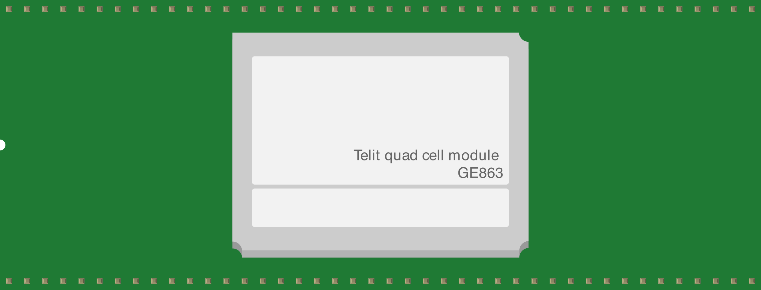
 Design with GE863 Cellular Module with GPS in Cirkit Designer
Introduction
The GE863 Cellular Module with GPS is a compact and versatile communication module designed for GSM/GPRS connectivity. It also features integrated GPS functionality, making it ideal for applications requiring both wireless communication and location tracking. Its small form factor and robust design make it suitable for embedded systems, IoT devices, and mobile applications.
Explore Projects Built with GE863 Cellular Module with GPS
 Open Project in Cirkit Designer
 Open Project in Cirkit Designer
 Open Project in Cirkit Designer
 Open Project in Cirkit Designer
Explore Projects Built with GE863 Cellular Module with GPS
Open Project in Cirkit DesignerOpen Project in Cirkit DesignerOpen Project in Cirkit DesignerOpen Project in Cirkit DesignerCommon Applications and Use Cases
- Vehicle tracking and fleet management
- Remote monitoring and telemetry systems
- IoT devices requiring cellular connectivity and GPS
- Emergency response systems
- Asset tracking and geofencing
Technical Specifications
Key Technical Details
| Parameter | Specification |
|---|---|
| Cellular Network Support | GSM/GPRS (Quad-band: 850/900/1800/1900 MHz) |
| GPS Support | Integrated GPS receiver |
| Data Transfer Rate | GPRS Class 10 (up to 85.6 kbps) |
| Operating Voltage | 3.6V to 4.2V |
| Power Consumption | Idle: ~2mA, Active: ~250mA |
| Dimensions | 41.4mm x 31.4mm x 3.6mm |
| Operating Temperature | -20°C to +55°C |
| Communication Interfaces | UART, SPI, I2C |
Pin Configuration and Descriptions
| Pin Number | Pin Name | Description |
|---|---|---|
| 1 | VCC | Power supply input (3.6V to 4.2V) |
| 2 | GND | Ground connection |
| 3 | TXD | UART Transmit Data |
| 4 | RXD | UART Receive Data |
| 5 | GPS_TX | GPS UART Transmit Data |
| 6 | GPS_RX | GPS UART Receive Data |
| 7 | RESET | Module reset (active low) |
| 8 | GPIO1 | General-purpose input/output pin |
| 9 | GPIO2 | General-purpose input/output pin |
| 10 | ANT | Antenna connection for GSM/GPRS |
| 11 | GPS_ANT | Antenna connection for GPS |
| 12 | ADC | Analog-to-digital converter input |
Usage Instructions
How to Use the GE863 in a Circuit
- Power Supply: Connect the VCC pin to a stable power source (3.6V to 4.2V) and the GND pin to the ground.
- Antenna Connections: Attach a GSM antenna to the
ANTpin and a GPS antenna to theGPS_ANTpin for optimal signal reception. - UART Communication: Use the
TXDandRXDpins to interface with a microcontroller or PC for GSM/GPRS communication. Similarly, use theGPS_TXandGPS_RXpins for GPS data. - Reset: Connect the
RESETpin to a microcontroller or a push-button for resetting the module when needed. - GPIO Pins: Utilize the GPIO pins for custom input/output operations as required by your application.
Important Considerations and Best Practices
- Ensure the power supply is stable and within the specified voltage range to avoid damage to the module.
- Use appropriate antennas for GSM and GPS to ensure reliable connectivity and location tracking.
- Place the module away from high-frequency noise sources to minimize interference.
- For UART communication, ensure the baud rate matches the module's default setting (typically 9600 bps) or configure it as needed.
- Use level shifters if interfacing with a microcontroller operating at a different voltage level.
Example: Connecting the GE863 to an Arduino UNO
Below is an example of how to interface the GE863 module with an Arduino UNO for sending an SMS and retrieving GPS coordinates.
Circuit Connections
- Connect
VCCto a 3.7V power source. - Connect
GNDto the Arduino's GND. - Connect
TXDto Arduino pin 10 (RX). - Connect
RXDto Arduino pin 11 (TX) via a voltage divider to step down the Arduino's 5V signal to 3.3V. - Connect
GPS_TXto Arduino pin 8 (RX for GPS). - Connect
GPS_RXto Arduino pin 9 (TX for GPS).
Arduino Code
#include <SoftwareSerial.h>

// Define software serial pins for GSM and GPS communication
SoftwareSerial gsmSerial(10, 11); // RX, TX for GSM
SoftwareSerial gpsSerial(8, 9);  // RX, TX for GPS

void setup() {
  // Initialize serial communication
  Serial.begin(9600);          // For debugging
  gsmSerial.begin(9600);       // GSM module baud rate
  gpsSerial.begin(9600);       // GPS module baud rate

  Serial.println("Initializing GE863 Module...");
  delay(1000);

  // Send AT command to check GSM module response
  gsmSerial.println("AT");
  delay(1000);
  while (gsmSerial.available()) {
    Serial.write(gsmSerial.read()); // Print GSM module response
  }

  // Send SMS example
  sendSMS("+1234567890", "Hello from GE863!");
}

void loop() {
  // Read GPS data
  if (gpsSerial.available()) {
    String gpsData = gpsSerial.readString();
    Serial.println("GPS Data: " + gpsData);
  }
}

void sendSMS(String phoneNumber, String message) {
  gsmSerial.println("AT+CMGF=1"); // Set SMS mode to text
  delay(1000);
  gsmSerial.println("AT+CMGS=\"" + phoneNumber + "\"");
  delay(1000);
  gsmSerial.println(message); // Message content
  delay(1000);
  gsmSerial.write(26); // Send Ctrl+Z to send the SMS
  delay(1000);
  Serial.println("SMS Sent!");
}
Troubleshooting and FAQs
Common Issues and Solutions
Module Not Responding to AT Commands
- Ensure the power supply is stable and within the specified range.
- Verify the UART connections and ensure the correct baud rate is set.
- Check if the
RESETpin is unintentionally held low.
Poor GSM Signal
- Ensure the GSM antenna is securely connected to the
ANTpin. - Relocate the module to an area with better network coverage.
- Ensure the GSM antenna is securely connected to the
GPS Not Acquiring Location
- Verify the GPS antenna is connected to the
GPS_ANTpin. - Place the module in an open area with a clear view of the sky for better satellite reception.
- Verify the GPS antenna is connected to the
High Power Consumption
- Check for unnecessary operations or peripherals consuming power.
- Use power-saving modes if supported by the module.
FAQs
Q: Can the GE863 module operate on 5V?
A: No, the module requires a power supply in the range of 3.6V to 4.2V. Using 5V may damage the module.
Q: What is the default baud rate for the UART interface?
A: The default baud rate is typically 9600 bps, but it can be configured as needed.
Q: Does the module support 3G or 4G networks?
A: No, the GE863 module supports only GSM/GPRS networks.
Q: Can I use the GPS and GSM functionalities simultaneously?
A: Yes, the module is designed to support simultaneous GSM communication and GPS tracking.