Cirkit Designer Logo
Cirkit Designer
Your all-in-one circuit design IDE
Home / 
Component Documentation

How to Use AS5600 magnetic encoder: Examples, Pinouts, and Specs

Image of AS5600 magnetic encoder
Cirkit Designer LogoDesign with AS5600 magnetic encoder in Cirkit Designer

Introduction

The AS5600 is a magnetic rotary position sensor that converts the angular position of a magnetic field to an analog or digital output signal. This contactless system is designed to measure the orientation of a magnetic field as perceived by the sensor. It is commonly used in applications requiring precise angle measurements, such as motor control, robotics, joysticks, and knob controls.

Explore Projects Built with AS5600 magnetic encoder

Use Cirkit Designer to design, explore, and prototype these projects online. Some projects support real-time simulation. Click "Open Project" to start designing instantly!
Arduino UNO with I2C Multiplexer and Multiple AS5600 Magnetic Encoders
Image of Thesis: A project utilizing AS5600 magnetic encoder in a practical application
This circuit consists of an Arduino UNO microcontroller interfaced with multiple AS5600 magnetic encoders through an Adafruit TCA9548A I2C multiplexer. The encoders are connected to different channels of the multiplexer, allowing the Arduino to communicate with each encoder individually over the I2C bus. The purpose of this circuit is to read multiple rotary positions simultaneously without I2C address conflicts, likely for precision control or feedback in a robotic or automation application.
Cirkit Designer LogoOpen Project in Cirkit Designer
Configurable Battery-Powered RF Signal Transmitter with DIP Switch Settings
Image of fyp transmitter: A project utilizing AS5600 magnetic encoder in a practical application
This circuit appears to be a configurable encoder system with an RF transmission capability. The encoder's address pins (A0-A7) are connected to a DIP switch for setting the address, and its data output (DO) is connected to an RF transmitter, allowing the encoded signal to be wirelessly transmitted. The circuit is powered by a 9V battery, regulated to 5V by a 7805 voltage regulator, and includes a diode for polarity protection. Tactile switches are connected to the encoder's data inputs (D1-D3), and an LED with a current-limiting resistor indicates power or activity.
Cirkit Designer LogoOpen Project in Cirkit Designer
Arduino Mega 2560 Based Position Tracking System with AS5048 Magnetic Encoder
Image of ME314: A project utilizing AS5600 magnetic encoder in a practical application
This circuit connects an AS5048 Magnetic Encoder Position Sensor to an Arduino Mega 2560 for position sensing. The sensor's power is supplied by the Arduino's 5V output, and its ground is connected to the Arduino's ground. The sensor's PWM output is connected to the Arduino's A0 analog input for reading the position values.
Cirkit Designer LogoOpen Project in Cirkit Designer
Rotary Encoder Interface with STG Adapter for Signal Processing
Image of Encoder in STG: A project utilizing AS5600 magnetic encoder in a practical application
The circuit consists of two rotary encoders (Kalamoyi P3022-V1-CW360) connected to two STG adapters. Each encoder's VCC, OUT, and GND pins are connected to the corresponding STG adapter, facilitating signal transmission and power supply management.
Cirkit Designer LogoOpen Project in Cirkit Designer

Explore Projects Built with AS5600 magnetic encoder

Use Cirkit Designer to design, explore, and prototype these projects online. Some projects support real-time simulation. Click "Open Project" to start designing instantly!
Image of Thesis: A project utilizing AS5600 magnetic encoder in a practical application
Arduino UNO with I2C Multiplexer and Multiple AS5600 Magnetic Encoders
This circuit consists of an Arduino UNO microcontroller interfaced with multiple AS5600 magnetic encoders through an Adafruit TCA9548A I2C multiplexer. The encoders are connected to different channels of the multiplexer, allowing the Arduino to communicate with each encoder individually over the I2C bus. The purpose of this circuit is to read multiple rotary positions simultaneously without I2C address conflicts, likely for precision control or feedback in a robotic or automation application.
Cirkit Designer LogoOpen Project in Cirkit Designer
Image of fyp transmitter: A project utilizing AS5600 magnetic encoder in a practical application
Configurable Battery-Powered RF Signal Transmitter with DIP Switch Settings
This circuit appears to be a configurable encoder system with an RF transmission capability. The encoder's address pins (A0-A7) are connected to a DIP switch for setting the address, and its data output (DO) is connected to an RF transmitter, allowing the encoded signal to be wirelessly transmitted. The circuit is powered by a 9V battery, regulated to 5V by a 7805 voltage regulator, and includes a diode for polarity protection. Tactile switches are connected to the encoder's data inputs (D1-D3), and an LED with a current-limiting resistor indicates power or activity.
Cirkit Designer LogoOpen Project in Cirkit Designer
Image of ME314: A project utilizing AS5600 magnetic encoder in a practical application
Arduino Mega 2560 Based Position Tracking System with AS5048 Magnetic Encoder
This circuit connects an AS5048 Magnetic Encoder Position Sensor to an Arduino Mega 2560 for position sensing. The sensor's power is supplied by the Arduino's 5V output, and its ground is connected to the Arduino's ground. The sensor's PWM output is connected to the Arduino's A0 analog input for reading the position values.
Cirkit Designer LogoOpen Project in Cirkit Designer
Image of Encoder in STG: A project utilizing AS5600 magnetic encoder in a practical application
Rotary Encoder Interface with STG Adapter for Signal Processing
The circuit consists of two rotary encoders (Kalamoyi P3022-V1-CW360) connected to two STG adapters. Each encoder's VCC, OUT, and GND pins are connected to the corresponding STG adapter, facilitating signal transmission and power supply management.
Cirkit Designer LogoOpen Project in Cirkit Designer

Technical Specifications

Key Technical Details

  • Supply Voltage (Vdd): 3.3V to 5V
  • Measurement Range: 0 to 360 degrees
  • Output Interface: Analog (0V to Vdd), PWM, I2C
  • Resolution: 12-bit (4096 positions)
  • Max Output Update Rate: 1 kHz (PWM), 100 Hz (I2C)
  • Operating Temperature Range: -40°C to +125°C

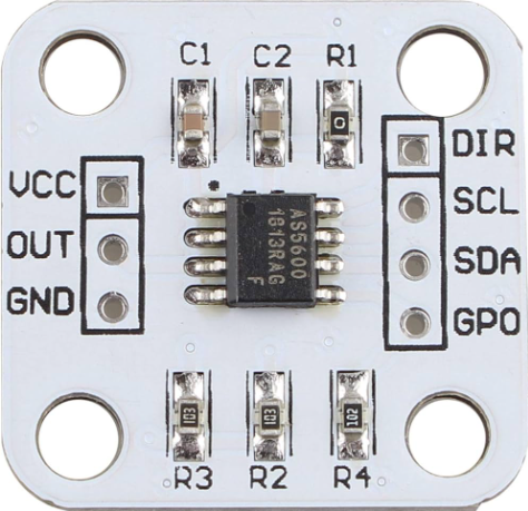
Pin Configuration and Descriptions

Pin Number Name Description
1 GND Ground connection
2 VDD Supply voltage (3.3V to 5V)
3 SCL I2C clock line
4 SDA I2C data line
5 OUT Analog/PWM output
6 VDD Supply voltage (duplicate for convenience)

Usage Instructions

Integration into a Circuit

  1. Power Supply: Connect the VDD pin to a 3.3V or 5V power supply and the GND pin to the ground.
  2. Output Selection: For analog output, connect the OUT pin to an analog input on your microcontroller. For PWM or I2C, ensure your microcontroller supports these interfaces and connect accordingly.
  3. Magnet Placement: Place a diametrically magnetized magnet above the sensor. The magnet's rotation axis should be perpendicular to the sensor surface.

Important Considerations and Best Practices

  • Magnet Type: Use a diametrically magnetized magnet for accurate measurements.
  • Magnet Distance: Keep the magnet within the recommended distance from the sensor surface as specified in the datasheet.
  • Calibration: Perform calibration through the I2C interface to account for magnet misalignment and variations.
  • Electromagnetic Interference: Avoid placing the sensor near strong electromagnetic fields to prevent interference.

Example Code for Arduino UNO

#include <Wire.h>

// AS5600 I2C address
#define AS5600_ADDRESS 0x36

// AS5600 register addresses
#define RAW_ANGLE_REG 0x0C

void setup() {
  Wire.begin(); // Initialize I2C
  Serial.begin(9600); // Start serial communication at 9600 baud
}

void loop() {
  unsigned int angle = readAS5600Angle();
  Serial.print("Angle: ");
  Serial.println(angle);
  delay(100); // Delay for readability
}

// Function to read the raw angle from the AS5600
unsigned int readAS5600Angle() {
  Wire.beginTransmission(AS5600_ADDRESS);
  Wire.write(RAW_ANGLE_REG); // Point to the raw angle register
  Wire.endTransmission(false);
  
  Wire.requestFrom(AS5600_ADDRESS, 2); // Request 2 bytes from the sensor
  while (Wire.available() < 2); // Wait for the data
  
  unsigned int angle = Wire.read(); // Read the first byte
  angle <<= 8; // Shift the first byte
  angle |= Wire.read(); // Read the second byte and combine with the first
  
  return angle;
}

Troubleshooting and FAQs

Common Issues

  • Inaccurate Readings: Ensure the magnet is properly aligned and within the specified distance from the sensor.
  • No Output Signal: Check the power supply and wiring connections. Verify that the magnet is present and correctly oriented.
  • Intermittent Signal: Check for loose connections and ensure the magnet is secured in place.

Solutions and Tips

  • Calibration: Use the I2C interface to calibrate the sensor for your specific setup.
  • Magnet Quality: Use a high-quality magnet to ensure consistent readings.
  • Shielding: Implement shielding or move the sensor away from other electronic components that may cause interference.

FAQs

Q: Can the AS5600 measure more than 360 degrees? A: No, the AS5600 is designed for 0 to 360-degree measurements.

Q: How do I calibrate the sensor? A: Calibration can be done through the I2C interface by writing to specific registers. Refer to the datasheet for detailed instructions.

Q: What is the maximum distance the magnet can be from the sensor? A: The maximum distance depends on the magnet strength but typically is a few millimeters. Consult the datasheet for exact specifications.

Q: Is the AS5600 affected by external magnetic fields? A: Yes, external magnetic fields can affect the readings. It is advisable to keep the sensor away from strong magnetic fields.