How to Use Divide by N Counter: Examples, Pinouts, and Specs

Introduction
The CD74HC4059E is a programmable "Divide by N" counter manufactured by Texas Instruments. This digital counter is designed to divide an input clock signal by an integer value N, resulting in an output signal with a frequency that is a fraction of the input frequency. This component is commonly used in applications such as frequency division, digital clocks, timers, and pulse generation.
Explore Projects Built with Divide by N Counter
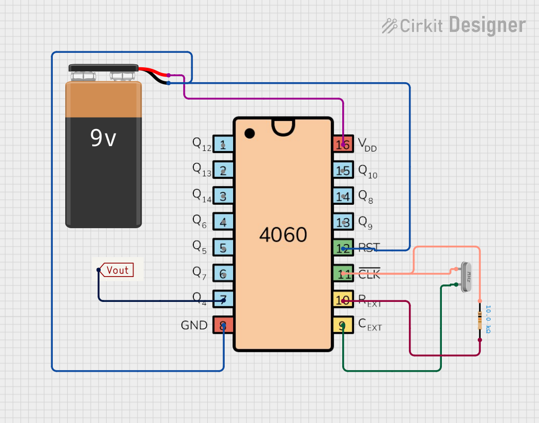
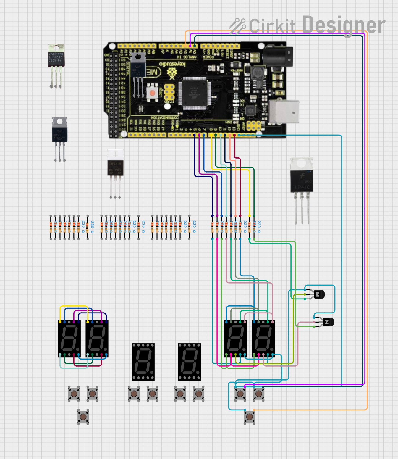
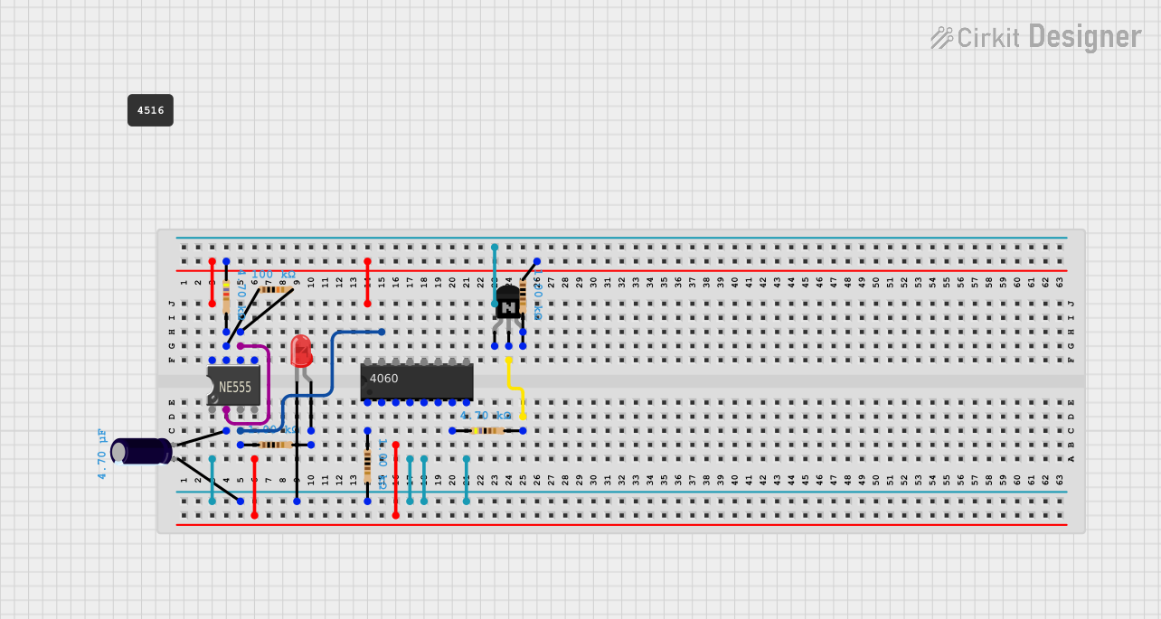
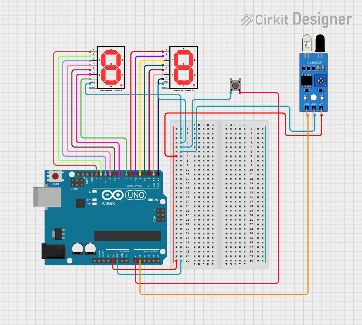
Explore Projects Built with Divide by N Counter
Technical Specifications
Key Technical Details
- Supply Voltage (Vcc): 2V to 6V
- Input Frequency (Max): 24MHz at Vcc = 6V
- Operating Temperature Range: -55°C to 125°C
- Output Current: ±5.2 mA
- Logic Family: HC
- Propagation Delay Time: 250ns at Vcc = 6V
- Package: 24-PDIP
Pin Configuration and Descriptions
| Pin Number | Name | Description |
|---|---|---|
| 1 | PE | Parallel Enable (active low) |
| 2-7 | P0-P5 | Parallel data inputs |
| 8 | GND | Ground (0V) |
| 9 | TC | Terminal Count (output) |
| 10 | TE | Terminal Enable (active low) |
| 11 | CE | Clock Enable (active low) |
| 12 | CCK | Clock input |
| 13 | CCKEN | Clock Enable (active high) |
| 14 | JAM | Jam (overrides counting) |
| 15-20 | Q0-Q5 | Flip-flop outputs |
| 21 | RCO | Ripple Carry Output (active high) |
| 22 | Vss | Positive Supply Voltage |
| 23 | RESET | Master Reset (active high) |
| 24 | Vcc | Positive Supply Voltage |
Usage Instructions
How to Use the CD74HC4059E in a Circuit
- Power Supply: Connect Vcc to a positive supply voltage between 2V and 6V and GND to the ground of your circuit.
- Clock Input: Apply the clock signal to the CCK pin. Ensure that the frequency does not exceed the maximum specified for your Vcc.
- Setting the Division Factor (N): Connect the parallel data inputs (P0-P5) to either Vcc or GND to set the binary value of N.
- Enabling the Counter: Ensure that CE and TE are held low to enable counting. If CCKEN is used, it must be held high.
- Resetting the Counter: Apply a high signal to the RESET pin to reset the counter to its initial state.
- Output: The divided frequency can be observed at the TC pin, and the current count can be read from the Q0-Q5 outputs.
Important Considerations and Best Practices
- Always ensure that the power supply is within the specified range to prevent damage to the component.
- Unused inputs should be tied to an appropriate logic level (Vcc or GND).
- Decoupling capacitors should be used near the power supply pins to filter out noise.
- Avoid exposing the counter to conditions that exceed the absolute maximum ratings.
Troubleshooting and FAQs
Common Issues
- Counter Not Working: Ensure that all enable pins are set correctly and that the RESET pin is not inadvertently activated.
- Incorrect Output Frequency: Double-check the division factor set by the parallel data inputs and ensure that the clock signal is clean and within the specified frequency range.
Solutions and Tips
- If the counter is not responding, verify that the power supply is connected properly and within the specified voltage range.
- For issues with the output frequency, ensure that the division factor N is set correctly by checking the parallel data inputs.
- Use an oscilloscope to check the integrity of the clock signal. Noise or an unstable clock signal can cause improper counting.
FAQs
Q: Can the CD74HC4059E be used with an Arduino? A: Yes, the CD74HC4059E can be interfaced with an Arduino, provided that the operating voltage levels are compatible.
Q: What is the maximum division factor that can be set? A: The maximum division factor is 2^6 - 1, as there are 6 parallel data inputs.
Q: How can I reset the counter during operation? A: Apply a high signal to the RESET pin momentarily to reset the counter to its initial state.
Example Code for Arduino UNO
// Define the pins connected to the CD74HC4059E
#define CLOCK_PIN 3 // Connect to CCK pin
#define RESET_PIN 4 // Connect to RESET pin

void setup() {
  pinMode(CLOCK_PIN, OUTPUT);
  pinMode(RESET_PIN, OUTPUT);
  // Reset the counter at the beginning
  digitalWrite(RESET_PIN, HIGH);
  delay(10);
  digitalWrite(RESET_PIN, LOW);
}

void loop() {
  // Generate a clock signal
  digitalWrite(CLOCK_PIN, HIGH);
  delayMicroseconds(10); // High for 10 microseconds
  digitalWrite(CLOCK_PIN, LOW);
  delayMicroseconds(10); // Low for 10 microseconds
  // The above code generates a 50kHz clock signal
}
Note: This example assumes that the division factor N has been set using the parallel data inputs and that the counter's enable pins are appropriately connected for normal operation. The code generates a simple clock signal to drive the counter. Adjust the delay for the desired input clock frequency.