How to Use USB convert Serial port: Examples, Pinouts, and Specs
Introduction
The USB to Serial Port Converter is a versatile device that bridges the gap between modern USB interfaces and legacy serial communication ports (RS-232, UART, etc.). It enables seamless data transfer between USB-enabled devices, such as computers, and older devices that rely on serial communication. This component is widely used in industrial automation, embedded systems, and debugging tools.
Explore Projects Built with USB convert Serial port


Explore Projects Built with USB convert Serial port
Common Applications and Use Cases
- Connecting legacy serial devices (e.g., modems, industrial equipment) to modern computers.
- Debugging and programming microcontrollers via UART.
- Data logging and communication with sensors or other serial peripherals.
- Interfacing with serial-based communication protocols in embedded systems.
Technical Specifications
Key Technical Details
- USB Interface: USB 2.0 (compatible with USB 1.1 and USB 3.0)
- Serial Port Standards: RS-232, TTL UART (depending on the model)
- Baud Rate: Up to 1 Mbps (varies by model)
- Power Supply: Powered via USB (5V)
- Operating System Support: Windows, macOS, Linux
- Driver Support: FTDI, CH340, or Prolific drivers (depending on the chipset)
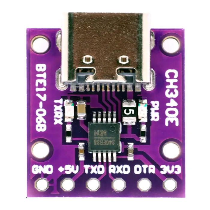
- Connector Types: USB Type-A or Type-C to DB9, or USB to pin headers for UART.
Pin Configuration and Descriptions
For USB to UART converters with pin headers, the pinout is typically as follows:
| Pin | Name | Description |
|---|---|---|
| 1 | GND | Ground reference for the circuit |
| 2 | TXD | Transmit data (output from the converter) |
| 3 | RXD | Receive data (input to the converter) |
| 4 | VCC | Power output (3.3V or 5V, depending on model) |
| 5 | RTS | Request to Send (optional, flow control) |
| 6 | CTS | Clear to Send (optional, flow control) |
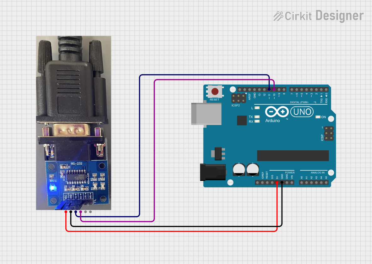
For USB to RS-232 converters with a DB9 connector, the pinout follows the RS-232 standard.
| Pin | Name | Description |
|---|---|---|
| 2 | RXD | Receive data (input to the converter) |
| 3 | TXD | Transmit data (output from the converter) |
| 5 | GND | Ground reference for the circuit |
| 7 | RTS | Request to Send (optional, flow control) |
| 8 | CTS | Clear to Send (optional, flow control) |
Usage Instructions
How to Use the Component in a Circuit
- Install Drivers: Ensure the appropriate driver (e.g., FTDI, CH340, or Prolific) is installed on your computer. Most operating systems will automatically detect and install the driver, but you can download it from the manufacturer's website if needed.
- Connect the Converter:
- For USB to UART: Connect the TXD pin of the converter to the RXD pin of the target device, and the RXD pin of the converter to the TXD pin of the target device. Connect GND to GND.
- For USB to RS-232: Use a standard DB9 cable to connect the converter to the serial device.
- Power the Circuit: If the target device requires power, ensure it is powered either through the VCC pin (for USB to UART) or an external power source.
- Open a Serial Terminal: Use a serial terminal application (e.g., PuTTY, Tera Term, or Arduino IDE Serial Monitor) to communicate with the device. Select the correct COM port and baud rate.
Important Considerations and Best Practices
- Voltage Levels: Ensure the voltage levels of the target device match the converter (e.g., 3.3V or 5V for UART). Using mismatched voltage levels can damage the device.
- Baud Rate Matching: Set the baud rate in the serial terminal to match the target device's baud rate for proper communication.
- Flow Control: If the target device uses hardware flow control (RTS/CTS), ensure the corresponding pins are connected and enabled in the software.
- Cable Length: Keep the USB and serial cables as short as possible to minimize signal degradation.
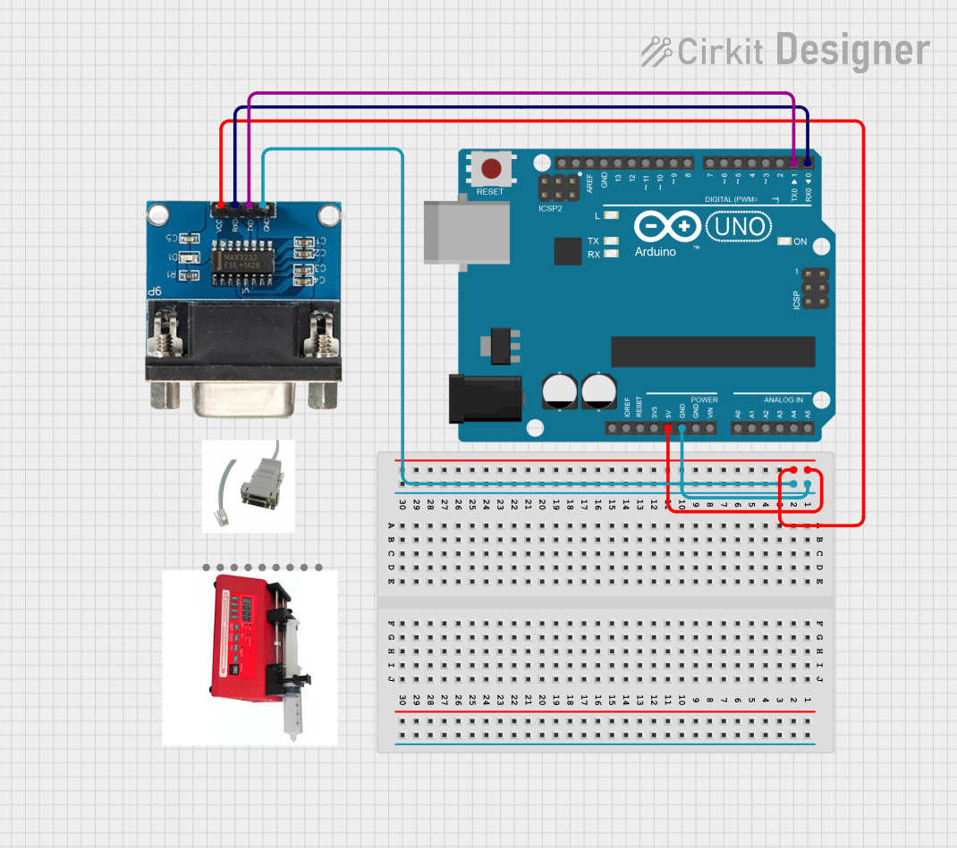
Example: Connecting to an Arduino UNO
The USB to Serial Port Converter can be used to program or debug an Arduino UNO via its UART pins. Below is an example Arduino sketch to test communication:
// Example sketch for testing USB to Serial communication
// This sketch echoes back any data received via the serial port.

void setup() {
  Serial.begin(9600); // Initialize serial communication at 9600 baud
  while (!Serial) {
    // Wait for the serial port to connect (for USB-based boards)
  }
  Serial.println("USB to Serial Converter Test");
}

void loop() {
  if (Serial.available() > 0) {
    // Read incoming data
    char received = Serial.read();
    // Echo the received data back to the sender
    Serial.print("Received: ");
    Serial.println(received);
  }
}
Upload this sketch to the Arduino UNO, then connect the USB to Serial Port Converter to the Arduino's RX and TX pins (cross-connect TXD to RX and RXD to TX). Open a serial terminal to test communication.
Troubleshooting and FAQs
Common Issues and Solutions
Device Not Recognized:
- Ensure the correct driver is installed for the converter's chipset.
- Try a different USB port or cable.
- Check the device manager (Windows) or system profiler (macOS) to verify the device is detected.
No Data Transmission:
- Verify the TXD and RXD connections are correctly cross-wired.
- Check the baud rate and other serial settings (e.g., parity, stop bits) in the terminal application.
- Ensure the target device is powered on.
Corrupted Data:
- Reduce the baud rate to improve signal integrity.
- Use shielded cables to minimize electromagnetic interference.
Driver Installation Fails:
- Download the latest driver from the manufacturer's website.
- Disable driver signature enforcement (Windows) if necessary.
FAQs
Q: Can I use this converter to program microcontrollers?
A: Yes, the USB to Serial Port Converter is commonly used to program microcontrollers like Arduino, ESP8266, and ESP32 via their UART interfaces.Q: What is the maximum cable length I can use?
A: For USB, the maximum recommended cable length is 5 meters. For RS-232, the maximum length depends on the baud rate but is typically up to 15 meters.Q: How do I know which driver to install?
A: Check the chipset used in your converter (e.g., FTDI, CH340, or Prolific) and download the corresponding driver from the manufacturer's website.Q: Can this converter provide power to my device?
A: Some USB to UART converters provide 3.3V or 5V output, but the current is limited. Check the specifications of your converter before powering a device.