Cirkit Designer Logo
Cirkit Designer
Your all-in-one circuit design IDE
Home / 
Component Documentation

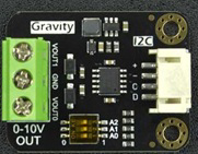
How to Use GP8403: Examples, Pinouts, and Specs

Image of GP8403
Cirkit Designer LogoDesign with GP8403 in Cirkit Designer

Introduction

The GP8403 is a high-performance, low-power integrated circuit (IC) designed for a wide range of applications, including power management and signal processing. Its versatile functionality and energy-efficient design make it an ideal choice for battery-operated devices. The GP8403 supports multiple operational modes, allowing it to adapt to various use cases with ease.

Explore Projects Built with GP8403

Use Cirkit Designer to design, explore, and prototype these projects online. Some projects support real-time simulation. Click "Open Project" to start designing instantly!
ESP32C3 and SIM800L Powered Smart Energy Monitor with OLED Display and Wi-Fi Connectivity
Image of SERVER: A project utilizing GP8403 in a practical application
This circuit is a power monitoring system that uses an ESP32C3 microcontroller to collect power usage data from slave devices via WiFi and SMS. The collected data is displayed on a 0.96" OLED screen, and the system is powered by an AC-DC converter module. Additionally, the circuit includes a SIM800L GSM module for SMS communication and LEDs for status indication.
Cirkit Designer LogoOpen Project in Cirkit Designer
Arduino Mega 2560 Based Security System with Fingerprint Authentication and SMS Alerts
Image of Door security system: A project utilizing GP8403 in a practical application
This circuit features an Arduino Mega 2560 microcontroller interfaced with a SIM800L GSM module, two fingerprint scanners, an I2C LCD display, an IR sensor, and a piezo buzzer. Power management is handled by a PowerBoost 1000 Basic Pad USB, a TP4056 charging module, and a Li-ion 18650 battery, with an option to use a Mini AC-DC 110V-230V to 5V 700mA module for direct power supply. The primary functionality appears to be a security system with GSM communication capabilities, biometric access control, and visual/audible feedback.
Cirkit Designer LogoOpen Project in Cirkit Designer
Cellular-Enabled IoT Device with Real-Time Clock and Power Management
Image of LRCM PHASE 2 BASIC: A project utilizing GP8403 in a practical application
This circuit features a LilyGo-SIM7000G module for cellular communication and GPS functionality, interfaced with an RTC DS3231 for real-time clock capabilities. It includes voltage sensing through two voltage sensor modules, and uses an 8-channel opto-coupler for isolating different parts of the circuit. Power management is handled by a buck converter connected to a DC power source and batteries, with a fuse for protection and a rocker switch for on/off control. Additionally, there's an LED for indication purposes.
Cirkit Designer LogoOpen Project in Cirkit Designer
ESP32-Based Accident Detection and GPS Tracking System with GSM Notifications
Image of hello: A project utilizing GP8403 in a practical application
This circuit features an ESP32 microcontroller interfaced with an MPU6050 accelerometer/gyroscope, a Neo 6M GPS module, and a SIM800L GSM module. The ESP32 communicates with the MPU6050 via I2C (SCL and SDA lines) to detect potential accidents based on acceleration thresholds, with the GPS module providing location data via a serial connection (RX0 and TX0). The SIM800L GSM module is connected to the ESP32 through another serial interface (RX2 and TX2) to send SMS alerts with location information in case of an accident detection.
Cirkit Designer LogoOpen Project in Cirkit Designer

Explore Projects Built with GP8403

Use Cirkit Designer to design, explore, and prototype these projects online. Some projects support real-time simulation. Click "Open Project" to start designing instantly!
Image of SERVER: A project utilizing GP8403 in a practical application
ESP32C3 and SIM800L Powered Smart Energy Monitor with OLED Display and Wi-Fi Connectivity
This circuit is a power monitoring system that uses an ESP32C3 microcontroller to collect power usage data from slave devices via WiFi and SMS. The collected data is displayed on a 0.96" OLED screen, and the system is powered by an AC-DC converter module. Additionally, the circuit includes a SIM800L GSM module for SMS communication and LEDs for status indication.
Cirkit Designer LogoOpen Project in Cirkit Designer
Image of Door security system: A project utilizing GP8403 in a practical application
Arduino Mega 2560 Based Security System with Fingerprint Authentication and SMS Alerts
This circuit features an Arduino Mega 2560 microcontroller interfaced with a SIM800L GSM module, two fingerprint scanners, an I2C LCD display, an IR sensor, and a piezo buzzer. Power management is handled by a PowerBoost 1000 Basic Pad USB, a TP4056 charging module, and a Li-ion 18650 battery, with an option to use a Mini AC-DC 110V-230V to 5V 700mA module for direct power supply. The primary functionality appears to be a security system with GSM communication capabilities, biometric access control, and visual/audible feedback.
Cirkit Designer LogoOpen Project in Cirkit Designer
Image of LRCM PHASE 2 BASIC: A project utilizing GP8403 in a practical application
Cellular-Enabled IoT Device with Real-Time Clock and Power Management
This circuit features a LilyGo-SIM7000G module for cellular communication and GPS functionality, interfaced with an RTC DS3231 for real-time clock capabilities. It includes voltage sensing through two voltage sensor modules, and uses an 8-channel opto-coupler for isolating different parts of the circuit. Power management is handled by a buck converter connected to a DC power source and batteries, with a fuse for protection and a rocker switch for on/off control. Additionally, there's an LED for indication purposes.
Cirkit Designer LogoOpen Project in Cirkit Designer
Image of hello: A project utilizing GP8403 in a practical application
ESP32-Based Accident Detection and GPS Tracking System with GSM Notifications
This circuit features an ESP32 microcontroller interfaced with an MPU6050 accelerometer/gyroscope, a Neo 6M GPS module, and a SIM800L GSM module. The ESP32 communicates with the MPU6050 via I2C (SCL and SDA lines) to detect potential accidents based on acceleration thresholds, with the GPS module providing location data via a serial connection (RX0 and TX0). The SIM800L GSM module is connected to the ESP32 through another serial interface (RX2 and TX2) to send SMS alerts with location information in case of an accident detection.
Cirkit Designer LogoOpen Project in Cirkit Designer

Common Applications

  • Power management in portable electronics
  • Signal processing in audio and communication devices
  • Battery-operated systems requiring low power consumption
  • Embedded systems and IoT devices

Technical Specifications

Key Technical Details

Parameter Value
Operating Voltage Range 2.7V to 5.5V
Quiescent Current 10 µA (typical)
Maximum Output Current 500 mA
Operating Temperature -40°C to +85°C
Package Type SOP-8 (Small Outline Package)

Pin Configuration and Descriptions

Pin Number Pin Name Description
1 VDD Power supply input (2.7V to 5.5V)
2 GND Ground connection
3 IN1 Input signal 1 for processing
4 IN2 Input signal 2 for processing
5 OUT1 Output signal 1
6 OUT2 Output signal 2
7 MODE Mode selection pin (low-power or high-performance)
8 EN Enable pin (active high to enable the IC)

Usage Instructions

How to Use the GP8403 in a Circuit

  1. Power Supply: Connect the VDD pin to a stable power source within the operating voltage range (2.7V to 5.5V). Connect the GND pin to the circuit ground.
  2. Input Signals: Feed the input signals to the IN1 and IN2 pins. Ensure the input signals are within the acceptable voltage levels specified in the datasheet.
  3. Output Signals: The processed signals will be available at the OUT1 and OUT2 pins. Connect these pins to the desired load or circuit.
  4. Mode Selection: Use the MODE pin to select the operational mode:
    • Pull the MODE pin low for low-power mode.
    • Pull the MODE pin high for high-performance mode.
  5. Enable the IC: Pull the EN pin high to enable the GP8403. Pull it low to disable the IC and reduce power consumption.

Important Considerations and Best Practices

  • Decoupling Capacitors: Place a 0.1 µF ceramic capacitor close to the VDD pin to filter out noise and ensure stable operation.
  • Thermal Management: Ensure adequate ventilation or heat dissipation if the IC operates near its maximum output current.
  • Signal Integrity: Use short and direct traces for input and output signals to minimize noise and signal degradation.
  • Mode Switching: Avoid rapid toggling of the MODE pin to prevent instability in the IC's operation.

Example: Connecting the GP8403 to an Arduino UNO

The GP8403 can be interfaced with an Arduino UNO for control and signal processing. Below is an example code snippet to enable the IC and toggle its mode:

// Define pin connections
const int enablePin = 7;  // Connect to the EN pin of GP8403
const int modePin = 8;    // Connect to the MODE pin of GP8403

void setup() {
  // Initialize pins as outputs
  pinMode(enablePin, OUTPUT);
  pinMode(modePin, OUTPUT);

  // Enable the GP8403
  digitalWrite(enablePin, HIGH);  // Set EN pin high to enable the IC

  // Set the GP8403 to high-performance mode
  digitalWrite(modePin, HIGH);   // Set MODE pin high for high-performance mode
}

void loop() {
  // Example: Toggle between modes every 5 seconds
  digitalWrite(modePin, LOW);    // Set MODE pin low for low-power mode
  delay(5000);                   // Wait for 5 seconds
  digitalWrite(modePin, HIGH);   // Set MODE pin high for high-performance mode
  delay(5000);                   // Wait for 5 seconds
}

Troubleshooting and FAQs

Common Issues and Solutions

  1. The IC does not power on:

    • Verify that the VDD pin is connected to a stable power source within the specified voltage range.
    • Check the GND connection for proper grounding.
  2. No output signal:

    • Ensure the EN pin is pulled high to enable the IC.
    • Verify that the input signals are within the acceptable voltage range.
    • Check the connections to the OUT1 and OUT2 pins for continuity.
  3. Excessive heat generation:

    • Ensure the load connected to the output pins does not exceed the maximum output current (500 mA).
    • Use proper heat dissipation techniques, such as a heat sink or adequate ventilation.
  4. Unstable operation:

    • Check for proper decoupling capacitor placement near the VDD pin.
    • Avoid rapid toggling of the MODE pin.

FAQs

Q: Can the GP8403 operate at 3.3V?
A: Yes, the GP8403 can operate within a voltage range of 2.7V to 5.5V, making it compatible with 3.3V systems.

Q: What happens if the EN pin is left floating?
A: The EN pin should not be left floating. It must be pulled high to enable the IC or pulled low to disable it.

Q: Can the GP8403 handle audio signal processing?
A: Yes, the GP8403 is suitable for signal processing applications, including audio signals, provided the input and output specifications are met.

Q: Is the GP8403 suitable for battery-powered devices?
A: Absolutely. Its low quiescent current (10 µA typical) and support for low-power mode make it ideal for battery-operated systems.