How to Use ESP32 (30 pin): Examples, Pinouts, and Specs
Introduction
The ESP32 is a powerful, low-cost microcontroller with built-in Wi-Fi and Bluetooth capabilities. It features 30 pins for various input/output (I/O) functions, making it an excellent choice for Internet of Things (IoT) applications, smart devices, and embedded systems. Its dual-core processor, extensive GPIO options, and support for multiple communication protocols make it versatile for a wide range of projects.
Explore Projects Built with ESP32 (30 pin)


Explore Projects Built with ESP32 (30 pin)
Common Applications and Use Cases
- IoT devices (e.g., smart home systems, sensors, and actuators)
- Wireless communication (Wi-Fi and Bluetooth-enabled projects)
- Data logging and monitoring systems
- Robotics and automation
- Wearable devices
- Prototyping and development of embedded systems
Technical Specifications
Key Technical Details
- Microcontroller: Tensilica Xtensa LX6 dual-core processor
- Clock Speed: Up to 240 MHz
- Flash Memory: 4 MB (varies by model)
- SRAM: 520 KB
- Wi-Fi: 802.11 b/g/n
- Bluetooth: v4.2 BR/EDR and BLE
- Operating Voltage: 3.3V
- Input Voltage Range: 5V (via USB) or 7-12V (via VIN pin)
- GPIO Pins: 30 pins (including ADC, DAC, PWM, I2C, SPI, UART)
- ADC Resolution: 12-bit
- DAC Resolution: 8-bit
- Power Consumption: Ultra-low power consumption in deep sleep mode (~10 µA)
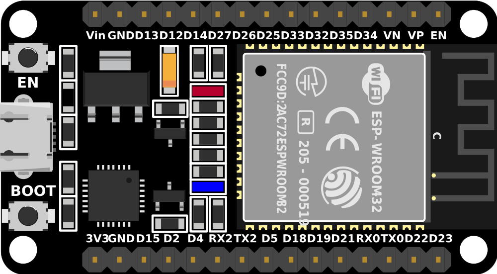
Pin Configuration and Descriptions
The ESP32 (30 pin) has a variety of pins for power, communication, and I/O. Below is a table summarizing the pin configuration:
| Pin Name | Function | Description |
|---|---|---|
| VIN | Power Input | Input voltage (7-12V) for powering the ESP32. |
| GND | Ground | Ground connection. |
| 3V3 | Power Output | Provides 3.3V output for external components. |
| EN | Enable | Enables or disables the chip (active high). |
| GPIO0 | I/O, Boot Mode Selection | General-purpose I/O, also used for boot mode selection during programming. |
| GPIO1 (TX0) | UART TX | UART0 transmit pin. |
| GPIO3 (RX0) | UART RX | UART0 receive pin. |
| GPIO2 | I/O, ADC, PWM | General-purpose I/O, ADC, or PWM output. |
| GPIO4 | I/O, ADC, PWM | General-purpose I/O, ADC, or PWM output. |
| GPIO5 | I/O, ADC, PWM | General-purpose I/O, ADC, or PWM output. |
| GPIO12-15 | I/O, ADC, PWM, Touch | General-purpose I/O, ADC, PWM, or capacitive touch input. |
| GPIO16-19 | I/O, SPI, ADC, PWM | General-purpose I/O, SPI communication, ADC, or PWM output. |
| GPIO21-23 | I/O, I2C, ADC, PWM | General-purpose I/O, I2C communication, ADC, or PWM output. |
| GPIO25-27 | I/O, ADC, DAC, PWM | General-purpose I/O, ADC, DAC, or PWM output. |
| GPIO32-39 | I/O, ADC, Touch | General-purpose I/O, ADC, or capacitive touch input. |
| TX2/RX2 | UART TX/RX | UART2 transmit and receive pins. |
| BOOT | Boot Mode Selection | Used to enter bootloader mode for programming. |
Note: Some GPIO pins have specific restrictions or are reserved for internal functions. Refer to the ESP32 datasheet for detailed pin behavior.
Usage Instructions
How to Use the ESP32 in a Circuit
Powering the ESP32:
- Use the VIN pin to supply 7-12V or connect a 5V USB power source.
- Ensure the 3.3V pin is used only for low-power external components.
Connecting Peripherals:
- Use GPIO pins for connecting sensors, actuators, or other peripherals.
- Configure pins as input or output in your code as needed.
Programming the ESP32:
- Install the ESP32 board package in the Arduino IDE or use the ESP-IDF framework.
- Connect the ESP32 to your computer via a USB cable.
- Select the correct board and port in the IDE, then upload your code.
Wi-Fi and Bluetooth Setup:
- Use the built-in libraries (
WiFi.handBluetoothSerial.h) to configure wireless communication.
- Use the built-in libraries (
Important Considerations and Best Practices
- Voltage Levels: The ESP32 operates at 3.3V logic levels. Avoid connecting 5V signals directly to GPIO pins.
- Boot Mode: Ensure GPIO0 is pulled low during programming to enter bootloader mode.
- Power Supply: Use a stable power source to avoid unexpected resets or instability.
- Deep Sleep Mode: Utilize deep sleep mode for battery-powered applications to conserve energy.
Example Code for Arduino UNO Integration
Below is an example of using the ESP32 to connect to a Wi-Fi network and send data to a server:
#include <WiFi.h> // Include the WiFi library

// Replace with your network credentials
const char* ssid = "Your_SSID";
const char* password = "Your_PASSWORD";

void setup() {
  Serial.begin(115200); // Initialize serial communication
  delay(1000);

  // Connect to Wi-Fi
  Serial.print("Connecting to Wi-Fi");
  WiFi.begin(ssid, password);
  while (WiFi.status() != WL_CONNECTED) {
    delay(500);
    Serial.print(".");
  }
  Serial.println("\nWi-Fi connected!");
  Serial.print("IP Address: ");
  Serial.println(WiFi.localIP()); // Print the ESP32's IP address
}

void loop() {
  // Add your main code here
}
Note: Replace
Your_SSIDandYour_PASSWORDwith your Wi-Fi network credentials.
Troubleshooting and FAQs
Common Issues and Solutions
ESP32 Not Connecting to Wi-Fi:
- Double-check the SSID and password.
- Ensure the router is within range and supports 2.4 GHz (ESP32 does not support 5 GHz).
Upload Fails in Arduino IDE:
- Ensure the correct board and port are selected in the IDE.
- Hold the BOOT button while uploading to enter bootloader mode.
Unstable Operation or Random Resets:
- Verify the power supply is stable and provides sufficient current (at least 500 mA).
- Avoid using GPIO pins reserved for internal functions.
GPIO Pin Not Working as Expected:
- Check if the pin is reserved or has specific restrictions.
- Ensure the pin is configured correctly in your code.
FAQs
Can the ESP32 operate on battery power? Yes, the ESP32 can be powered by a battery. Use deep sleep mode to extend battery life.
Does the ESP32 support Over-the-Air (OTA) updates? Yes, the ESP32 supports OTA updates, allowing you to upload new firmware wirelessly.
Can I use the ESP32 with 5V logic devices? No, the ESP32 operates at 3.3V logic levels. Use a level shifter if interfacing with 5V devices.
How do I reset the ESP32? Press the EN (enable) button to reset the ESP32.
This documentation provides a comprehensive guide to using the ESP32 (30 pin) microcontroller effectively. For more advanced features, refer to the official ESP32 datasheet and programming guides.