How to Use flourescent bulb: Examples, Pinouts, and Specs
Introduction
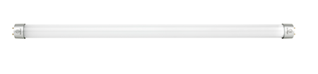
A fluorescent bulb is a type of light bulb that uses electricity to excite mercury vapor, which in turn produces short-wave ultraviolet light. This ultraviolet light causes a phosphor coating inside the bulb to glow, producing visible light. Fluorescent bulbs are known for their energy efficiency and long lifespan compared to traditional incandescent bulbs.
Explore Projects Built with flourescent bulb
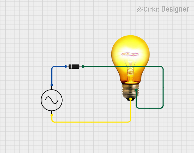
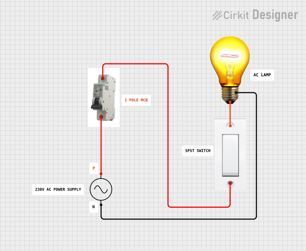

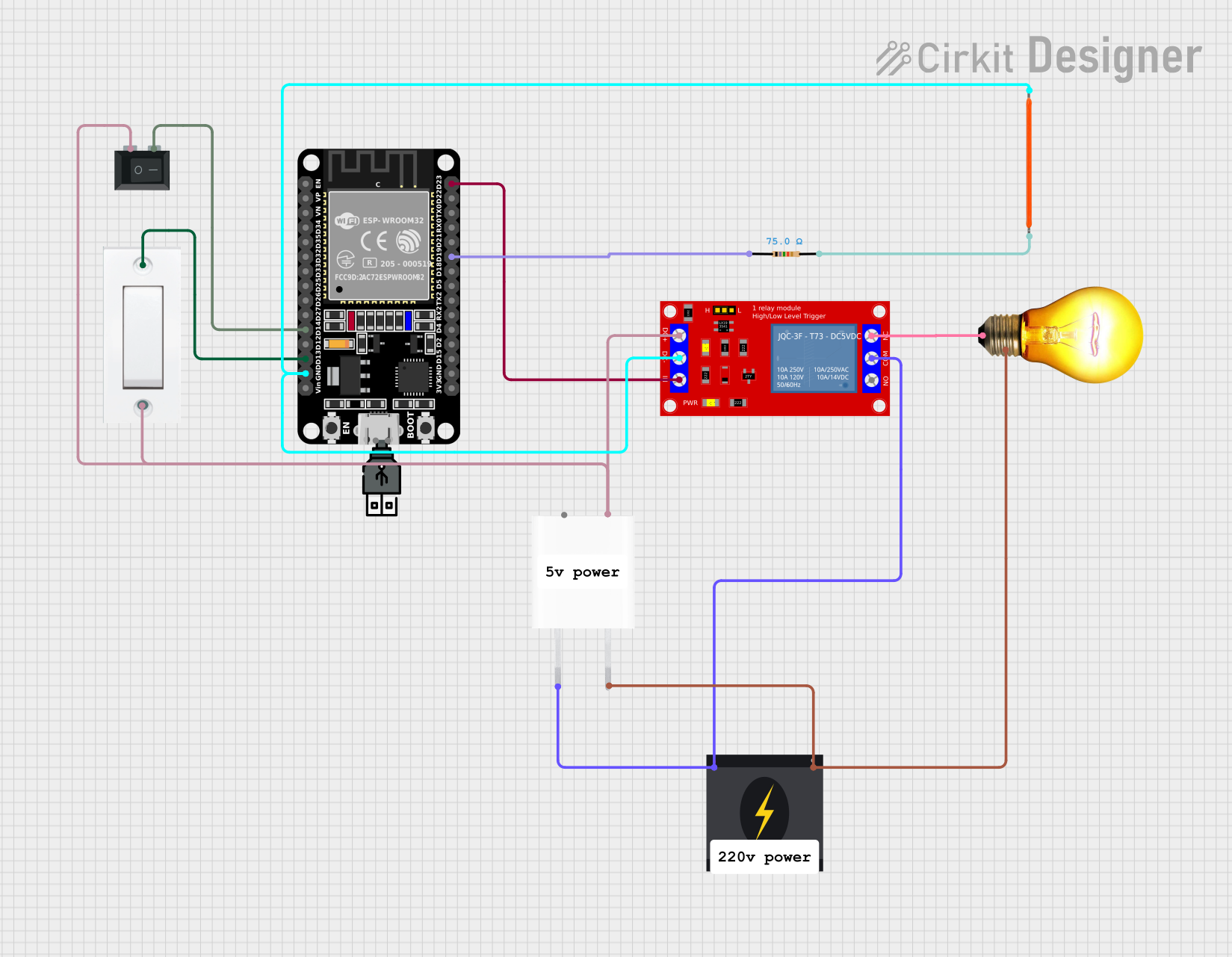
Explore Projects Built with flourescent bulb
Common Applications and Use Cases
- Residential Lighting: Used in homes for general lighting purposes.
- Commercial Lighting: Commonly used in offices, retail stores, and other commercial spaces.
- Industrial Lighting: Utilized in factories and warehouses for bright, efficient lighting.
- Public Spaces: Found in schools, hospitals, and other public buildings.
- Specialty Lighting: Used in applications requiring specific light qualities, such as grow lights for plants.
Technical Specifications
Key Technical Details
| Parameter | Value |
|---|---|
| Voltage | 120V AC (common household) |
| Current | 0.32A (typical for 40W bulb) |
| Power Rating | 40W |
| Luminous Efficacy | 50-100 lumens per watt |
| Color Temperature | 2700K to 6500K |
| Lifespan | 7,000 to 15,000 hours |
| Base Type | G13 (for T8 tube) |
Pin Configuration and Descriptions
| Pin Number | Description |
|---|---|
| 1 | Cathode (connected to ballast) |
| 2 | Cathode (connected to ballast) |
| 3 | Anode (connected to ballast) |
| 4 | Anode (connected to ballast) |
Usage Instructions
How to Use the Component in a Circuit
- Ballast Connection: Fluorescent bulbs require a ballast to regulate the current through the lamp. Connect the ballast to the power source and the bulb.
- Starter Connection: Some fluorescent bulbs require a starter to initiate the lighting process. Connect the starter in series with the bulb.
- Wiring: Ensure that the wiring is done correctly according to the ballast and starter specifications. Incorrect wiring can lead to malfunction or damage.
- Mounting: Secure the bulb in a suitable fixture designed for fluorescent bulbs. Ensure that the fixture is rated for the bulb's power rating.
Important Considerations and Best Practices
- Safety First: Always disconnect the power before installing or replacing a fluorescent bulb.
- Proper Disposal: Fluorescent bulbs contain mercury and should be disposed of properly according to local regulations.
- Avoid Frequent Switching: Frequent on/off switching can reduce the lifespan of the bulb.
- Use Compatible Ballasts: Ensure that the ballast is compatible with the type and power rating of the fluorescent bulb.
Troubleshooting and FAQs
Common Issues Users Might Face
Bulb Flickering:
- Cause: Faulty ballast, loose connections, or end-of-life bulb.
- Solution: Check and secure connections, replace the ballast, or replace the bulb.
Bulb Not Lighting:
- Cause: Faulty starter, ballast, or bulb.
- Solution: Replace the starter, check the ballast, or replace the bulb.
Dim Light Output:
- Cause: Aging bulb, dirty fixture, or low voltage.
- Solution: Clean the fixture, check the voltage, or replace the bulb.
Solutions and Tips for Troubleshooting
- Check Connections: Ensure all electrical connections are secure and free from corrosion.
- Test Components: Use a multimeter to test the continuity of the starter and ballast.
- Replace Components: If a component is found to be faulty, replace it with a compatible part.
- Consult Manuals: Refer to the ballast and fixture manuals for specific troubleshooting steps.
Arduino UNO Integration (Optional)
While fluorescent bulbs are not typically controlled by microcontrollers like the Arduino UNO, you can use a relay module to switch the bulb on and off. Below is an example code to control a relay module connected to an Arduino UNO:
// Arduino UNO code to control a relay module for a fluorescent bulb

const int relayPin = 7; // Pin connected to the relay module

void setup() {
  pinMode(relayPin, OUTPUT); // Set relay pin as an output
  digitalWrite(relayPin, LOW); // Ensure relay is off at startup
}

void loop() {
  digitalWrite(relayPin, HIGH); // Turn on the relay (and the bulb)
  delay(5000); // Keep the bulb on for 5 seconds
  digitalWrite(relayPin, LOW); // Turn off the relay (and the bulb)
  delay(5000); // Keep the bulb off for 5 seconds
}
In this example, the relay module is connected to pin 7 of the Arduino UNO. The code turns the relay (and the connected fluorescent bulb) on and off every 5 seconds. Ensure that the relay module is rated for the voltage and current of the fluorescent bulb.
By following this documentation, users can effectively utilize and troubleshoot fluorescent bulbs in various applications.