How to Use Adafruit bq25185 USB / DC / Solar Charger with 5V Boost Board: Examples, Pinouts, and Specs
Adafruit bq25185 USB / DC / Solar Charger with 5V Boost Board
1. Introduction
The Adafruit bq25185 USB / DC / Solar Charger with 5V Boost Board is a versatile and compact charging solution designed for a wide range of applications. It supports multiple power input sources, including USB, DC, and solar panels, making it ideal for portable and renewable energy projects. The board features a highly efficient 5V boost converter, enabling it to charge batteries and simultaneously power devices. Its small form factor and robust design make it suitable for IoT devices, wearables, and low-power embedded systems.
Common Applications:
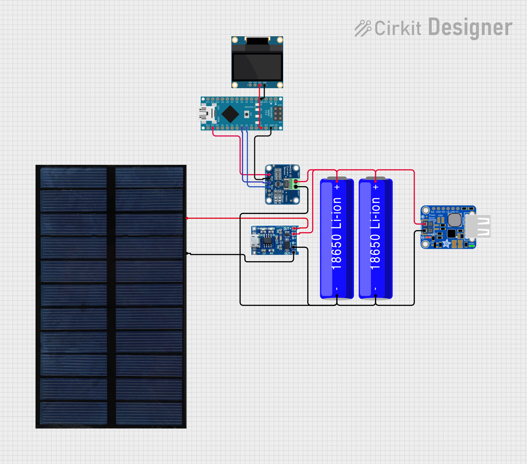
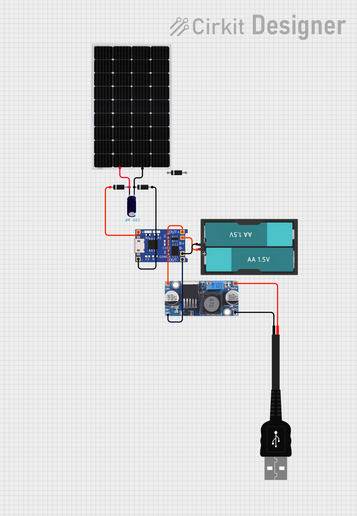
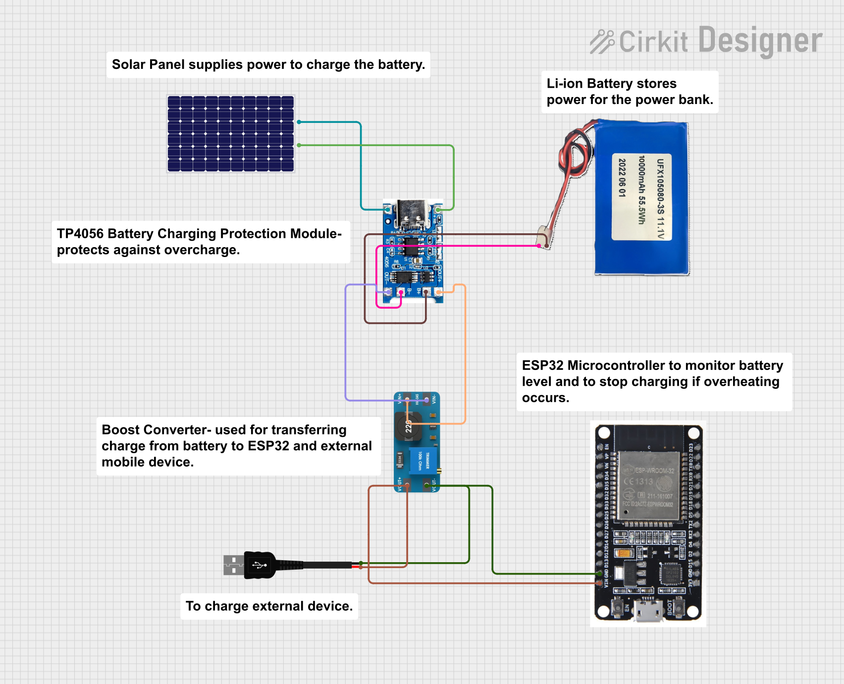
- Solar-powered IoT devices
- Wearable electronics
- Battery-powered embedded systems
- Portable chargers and power banks
- Low-power robotics and automation
2. Technical Specifications
The following table outlines the key technical details of the Adafruit bq25185 board:
| Parameter | Specification |
|---|---|
| Input Voltage Range | 3.5V to 6.5V (USB, DC, or solar input) |
| Battery Charging Voltage | Configurable: 4.2V (default for Li-Ion/Li-Po batteries) |
| Battery Charging Current | Configurable: Up to 500mA |
| Boost Converter Output | 5V @ 1A (max) |
| Battery Type Supported | Single-cell Li-Ion or Li-Po |
| Operating Temperature | -40°C to +85°C |
| Dimensions | 25mm x 20mm x 5mm |
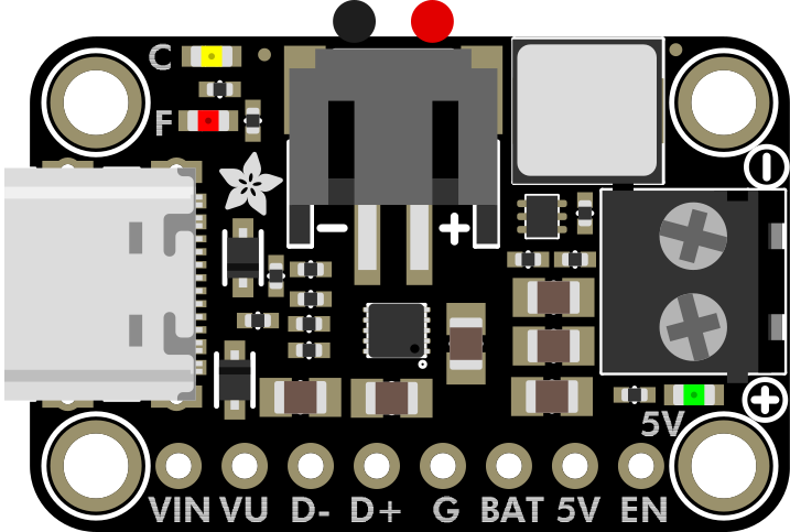
Pin Configuration and Descriptions
| Pin Name | Type | Description |
|---|---|---|
| VIN | Power Input | Main power input (3.5V to 6.5V). Connect USB, DC, or solar panel here. |
| GND | Ground | Ground connection for the circuit. |
| BAT | Power Input/Output | Connect to the positive terminal of the Li-Ion/Li-Po battery. |
| 5V | Power Output | 5V regulated output from the boost converter. |
| EN | Input | Enable pin for the boost converter. Pull high to enable, low to disable. |
| PG | Output | Power Good indicator. High when input power is available. |
| CHG | Output | Charging status indicator. Low when charging, high when charging is complete. |
| I2C SDA | Data Line | I2C data line for communication with a microcontroller. |
| I2C SCL | Clock Line | I2C clock line for communication with a microcontroller. |
3. Usage Instructions
Connecting the Board
Power Input:
- Connect a USB cable, DC power source, or solar panel to the VIN pin.
- Ensure the input voltage is within the range of 3.5V to 6.5V.
Battery Connection:
- Connect a single-cell Li-Ion or Li-Po battery to the BAT pin.
- Ensure correct polarity to avoid damage to the board or battery.
Load Connection:
- Connect your device or circuit to the 5V pin for a regulated 5V output.
Enable Boost Converter:
- Pull the EN pin high to enable the 5V boost converter.
Important Considerations:
- Use a properly rated battery to avoid overcharging or overheating.
- If using a solar panel, ensure it provides sufficient voltage and current under typical lighting conditions.
- Avoid shorting the BAT or 5V pins to ground, as this may damage the board.
4. Example Arduino Code
The Adafruit bq25185 board can be interfaced with an Arduino UNO via the I2C interface for monitoring and control. Below is an example code to read the charging status and battery voltage:
#include <Wire.h>

// I2C address of the bq25185 charger
#define BQ25185_I2C_ADDRESS 0x6B

void setup() {
  Serial.begin(9600); // Initialize serial communication
  Wire.begin();       // Initialize I2C communication

  Serial.println("Adafruit bq25185 Charger Example");
}

void loop() {
  // Read charging status
  Wire.beginTransmission(BQ25185_I2C_ADDRESS);
  Wire.write(0x0B); // Register address for charging status
  Wire.endTransmission(false);
  Wire.requestFrom(BQ25185_I2C_ADDRESS, 1);

  if (Wire.available()) {
    uint8_t status = Wire.read();
    Serial.print("Charging Status: ");
    if (status & 0x01) {
      Serial.println("Charging");
    } else {
      Serial.println("Not Charging");
    }
  }

  // Read battery voltage
  Wire.beginTransmission(BQ25185_I2C_ADDRESS);
  Wire.write(0x0C); // Register address for battery voltage
  Wire.endTransmission(false);
  Wire.requestFrom(BQ25185_I2C_ADDRESS, 2);

  if (Wire.available() == 2) {
    uint16_t voltage = Wire.read() << 8 | Wire.read();
    float batteryVoltage = voltage * 0.00125; // Convert to volts
    Serial.print("Battery Voltage: ");
    Serial.print(batteryVoltage);
    Serial.println(" V");
  }

  delay(1000); // Wait 1 second before the next reading
}
Code Explanation:
- The I2C address of the bq25185 is
0x6B. - Register
0x0Bis used to read the charging status. - Register
0x0Cis used to read the battery voltage. - The battery voltage is calculated by multiplying the raw value by
0.00125(based on the datasheet).
5. Troubleshooting and FAQs
Common Issues and Solutions
| Issue | Possible Cause | Solution |
|---|---|---|
| Board not powering up | Incorrect input voltage | Ensure the input voltage is between 3.5V and 6.5V. |
| Battery not charging | Battery not connected properly | Check the battery connection and polarity. |
| No 5V output | Boost converter disabled | Ensure the EN pin is pulled high. |
| Inconsistent solar charging | Insufficient sunlight or panel output | Use a higher-efficiency solar panel or improve lighting conditions. |
| I2C communication failure | Incorrect wiring or address mismatch | Verify I2C connections and ensure the correct I2C address is used. |
Frequently Asked Questions
Can I use this board without a battery?
- Yes, the board can provide a 5V output directly from the input source, but a battery is recommended for stable operation.
What type of solar panel should I use?
- Use a solar panel with an output voltage of 5V to 6V and a current rating of at least 500mA.
How do I configure the charging current?
- The charging current can be configured via I2C commands. Refer to the bq25185 datasheet for detailed instructions.
Is the board protected against overcharging?
- Yes, the bq25185 includes built-in overcharge protection for Li-Ion/Li-Po batteries.
This documentation provides a comprehensive guide to using the Adafruit bq25185 USB / DC / Solar Charger with 5V Boost Board. For further details, refer to the official Adafruit product page.
Explore Projects Built with Adafruit bq25185 USB / DC / Solar Charger with 5V Boost Board

Explore Projects Built with Adafruit bq25185 USB / DC / Solar Charger with 5V Boost Board