
How to Use Raspberry Pi 4B: Examples, Pinouts, and Specs
 Design with Raspberry Pi 4B in Cirkit Designer
Introduction
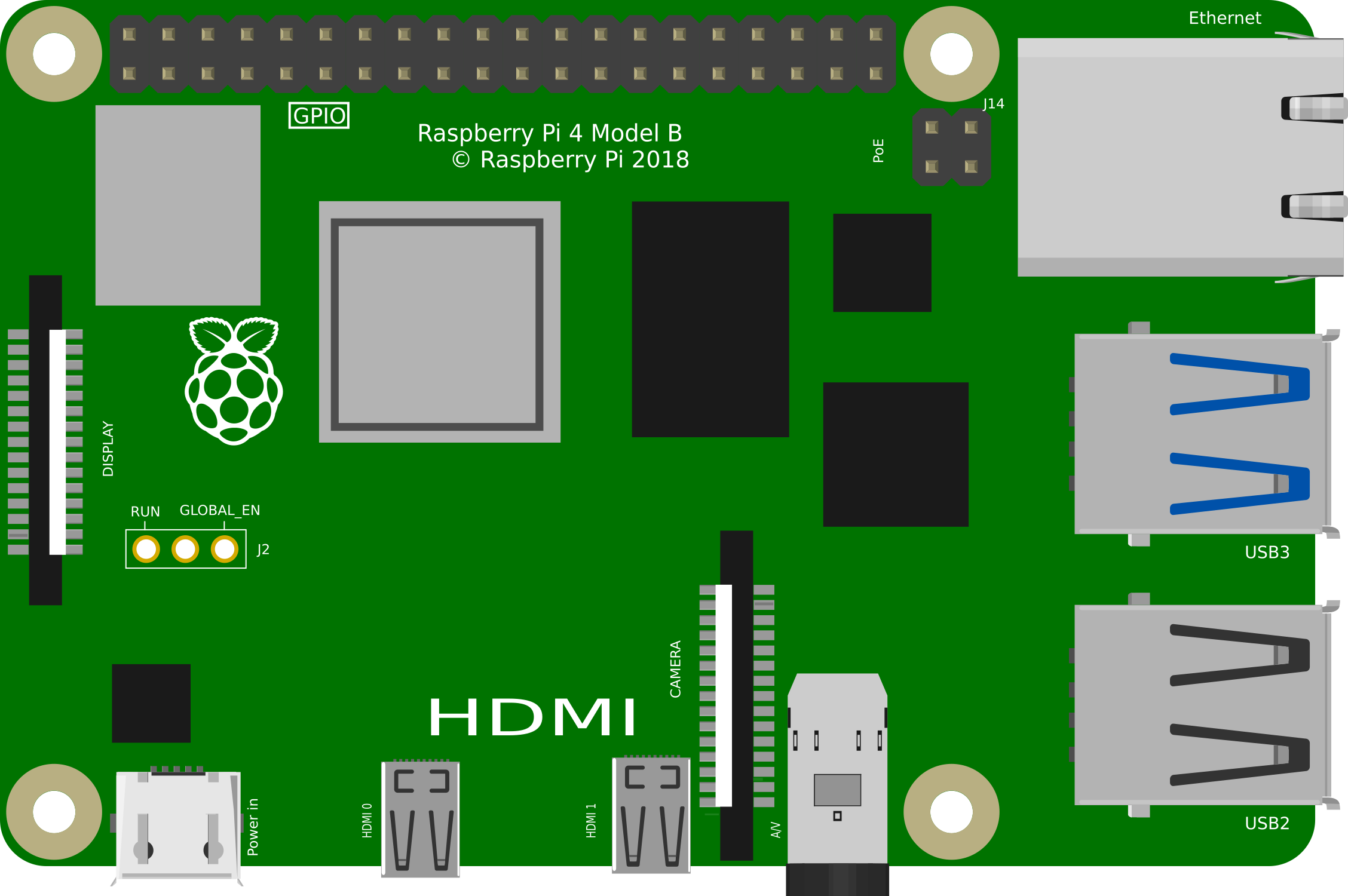
The Raspberry Pi 4B is a compact, affordable single-board computer designed for a wide range of applications. It features a powerful quad-core processor, up to 8GB of RAM, USB 3.0 ports, dual micro-HDMI outputs, and built-in wireless connectivity. This versatile device is ideal for programming, media centers, IoT (Internet of Things) projects, robotics, and more. Its small form factor and robust performance make it a popular choice for hobbyists, educators, and professionals alike.
Explore Projects Built with Raspberry Pi 4B
 Open Project in Cirkit Designer
 Open Project in Cirkit Designer
 Open Project in Cirkit Designer
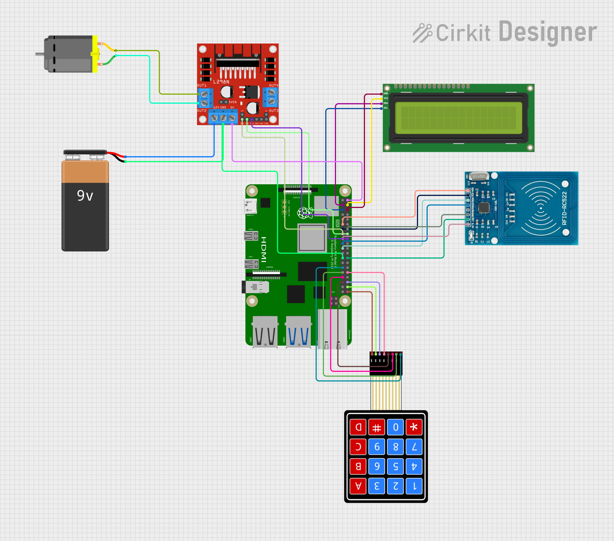 Open Project in Cirkit Designer
Explore Projects Built with Raspberry Pi 4B
Open Project in Cirkit DesignerOpen Project in Cirkit DesignerOpen Project in Cirkit DesignerOpen Project in Cirkit DesignerCommon Applications and Use Cases
- Programming and Development: Ideal for learning programming languages like Python, Java, and C++.
- Media Centers: Can be used to build a home theater system with software like Kodi.
- IoT Projects: Acts as a hub for smart home devices or other IoT applications.
- Robotics: Powers robots with its GPIO pins and processing capabilities.
- Education: Widely used in schools for teaching computer science and electronics.
- Web Servers: Can host lightweight web servers for personal or small-scale projects.
Technical Specifications
The Raspberry Pi 4B offers a range of features and capabilities. Below are its key technical details:
Key Technical Details
| Specification | Details |
|---|---|
| Processor | Quad-core Cortex-A72 (ARM v8) 64-bit SoC @ 1.5GHz |
| RAM Options | 2GB, 4GB, or 8GB LPDDR4 |
| Storage | MicroSD card slot (supports up to 1TB) |
| USB Ports | 2x USB 3.0, 2x USB 2.0 |
| Video Output | 2x micro-HDMI ports (supports up to 4K resolution) |
| Networking | Gigabit Ethernet, 802.11ac Wi-Fi, Bluetooth 5.0 |
| GPIO Pins | 40-pin GPIO header (3.3V logic) |
| Power Supply | 5V/3A via USB-C or GPIO header |
| Dimensions | 85.6mm x 56.5mm x 17mm |
| Operating System | Raspberry Pi OS (formerly Raspbian), supports other Linux distributions |
GPIO Pin Configuration
The Raspberry Pi 4B features a 40-pin GPIO header. Below is a summary of the pin configuration:
| Pin Number | Function | Description |
|---|---|---|
| 1 | 3.3V Power | Power supply (3.3V) |
| 2 | 5V Power | Power supply (5V) |
| 3 | GPIO 2 (SDA1) | I2C Data |
| 4 | 5V Power | Power supply (5V) |
| 5 | GPIO 3 (SCL1) | I2C Clock |
| 6 | Ground | Ground |
| ... | ... | ... |
| 39 | Ground | Ground |
| 40 | GPIO 21 | General Purpose I/O |
For a complete GPIO pinout, refer to the official Raspberry Pi documentation.
Usage Instructions
How to Use the Raspberry Pi 4B in a Circuit
Powering the Raspberry Pi:
- Use a 5V/3A USB-C power supply to power the Raspberry Pi 4B.
- Alternatively, power it via the GPIO header (pins 2 and 6 for 5V and ground).
Connecting Peripherals:
- Attach a micro-HDMI cable to connect the Raspberry Pi to a monitor.
- Connect a USB keyboard and mouse to the USB ports.
- Insert a microSD card with the operating system installed into the microSD card slot.
Using GPIO Pins:
- Use the GPIO pins to interface with sensors, LEDs, motors, and other components.
- Ensure proper voltage levels (3.3V logic) to avoid damaging the board.
Networking:
- Connect to the internet via Ethernet or Wi-Fi for software updates and remote access.
Important Considerations and Best Practices
- Cooling: The Raspberry Pi 4B can get hot under heavy loads. Use a heatsink or fan for cooling.
- Power Supply: Ensure a stable 5V/3A power supply to avoid performance issues.
- Static Electricity: Handle the board carefully to prevent damage from static discharge.
- Software Updates: Regularly update the operating system and software for optimal performance and security.
Example: Blinking an LED with GPIO and Python
Below is an example of how to blink an LED using the GPIO pins and Python:
Import the necessary library for GPIO control
import RPi.GPIO as GPIO import time
Set up GPIO mode (BCM numbering)
GPIO.setmode(GPIO.BCM)
Define the GPIO pin connected to the LED
LED_PIN = 18
Set up the LED pin as an output
GPIO.setup(LED_PIN, GPIO.OUT)
try: while True: GPIO.output(LED_PIN, GPIO.HIGH) # Turn the LED on time.sleep(1) # Wait for 1 second GPIO.output(LED_PIN, GPIO.LOW) # Turn the LED off time.sleep(1) # Wait for 1 second except KeyboardInterrupt: # Clean up GPIO settings before exiting GPIO.cleanup()
Running the Code
- Connect an LED to GPIO pin 18 and ground (use a resistor to limit current).
- Save the code to a file (e.g.,
blink.py). - Run the script using the command:
python3 blink.py.
Troubleshooting and FAQs
Common Issues and Solutions
The Raspberry Pi does not boot:
- Ensure the microSD card is properly inserted and contains a valid operating system.
- Check the power supply for sufficient voltage and current.
Overheating:
- Use a heatsink or fan to cool the Raspberry Pi.
- Avoid placing the board in an enclosed space without ventilation.
No display on the monitor:
- Verify the micro-HDMI cable is securely connected.
- Ensure the monitor is set to the correct input source.
- Check for compatibility with the monitor's resolution.
GPIO pins not working:
- Double-check the wiring and connections.
- Ensure the correct GPIO pin numbering is used in the code.
- Verify that the GPIO pins are not damaged.
FAQs
Can I power the Raspberry Pi 4B with a power bank? Yes, as long as the power bank provides a stable 5V/3A output.
What operating systems are supported? The Raspberry Pi 4B supports Raspberry Pi OS, Ubuntu, and other Linux distributions.
Can I connect multiple displays? Yes, the Raspberry Pi 4B supports dual displays via its two micro-HDMI ports.
How do I reset the Raspberry Pi? Simply unplug and replug the power supply to restart the device.
For additional support, refer to the official Raspberry Pi documentation or community forums.