
How to Use drive gauche: Examples, Pinouts, and Specs
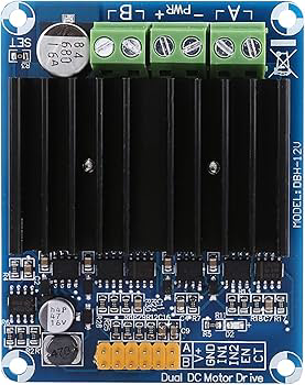
 Design with drive gauche in Cirkit Designer
Introduction
The Drive Gauche is a mechanical component commonly used in vehicles, machinery, and automation systems. It refers to a left-hand drive mechanism designed to facilitate movement or control in a specific direction. This component is essential in applications where precise directional control or torque transfer is required. Its robust design and adaptability make it suitable for a wide range of industrial and automotive use cases.
Explore Projects Built with drive gauche
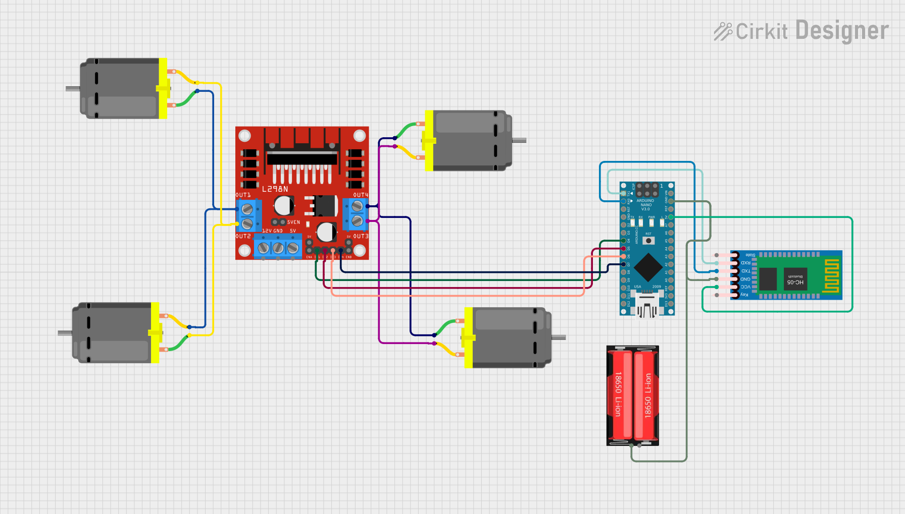 Open Project in Cirkit Designer
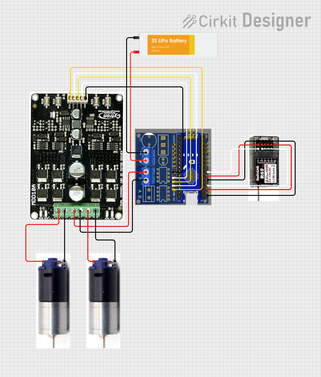 Open Project in Cirkit Designer
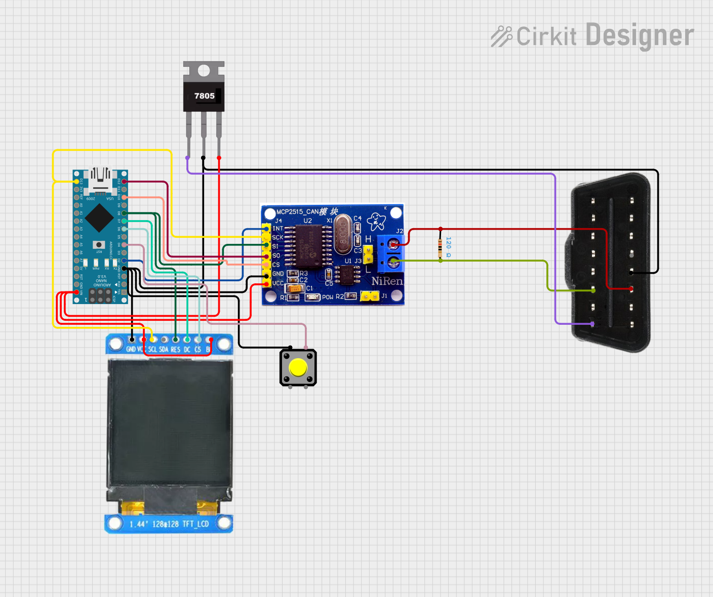 Open Project in Cirkit Designer
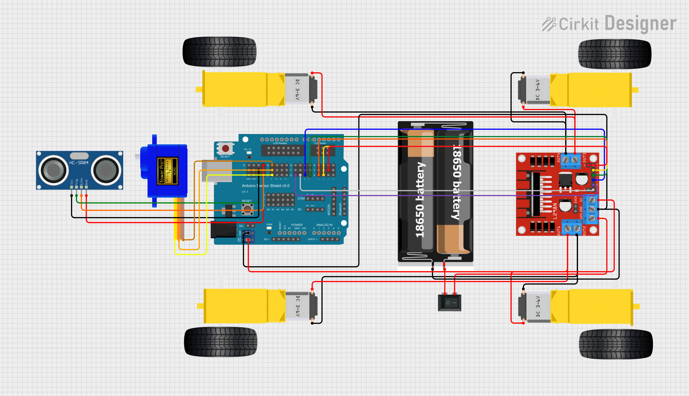 Open Project in Cirkit Designer
Explore Projects Built with drive gauche
Open Project in Cirkit DesignerOpen Project in Cirkit DesignerOpen Project in Cirkit DesignerOpen Project in Cirkit DesignerCommon Applications:
- Left-hand drive systems in vehicles
- Conveyor belt mechanisms in manufacturing
- Robotic arms and automation systems
- Heavy machinery requiring directional torque control
Technical Specifications
The Drive Gauche is designed to meet the demands of various mechanical systems. Below are its key technical specifications:
General Specifications
| Parameter | Value |
|---|---|
| Material | High-strength steel or alloy |
| Drive Orientation | Left-hand (counterclockwise) |
| Torque Capacity | Up to 500 Nm |
| Operating Temperature | -20°C to 120°C |
| Weight | 2.5 kg |
| Dimensions (L x W x H) | 150 mm x 80 mm x 60 mm |
Pin Configuration and Descriptions
For systems where the Drive Gauche integrates with electronic or electromechanical components, the following pin configuration is typical:
| Pin Number | Pin Name | Description |
|---|---|---|
| 1 | Power Input | Supplies power to the drive mechanism |
| 2 | Ground | Connects to the system ground |
| 3 | Control Signal | Receives control signals for directional input |
| 4 | Feedback | Outputs feedback for monitoring (e.g., position) |
Usage Instructions
To use the Drive Gauche effectively in a system, follow these steps:
Mechanical Installation:
- Secure the Drive Gauche to the mounting surface using appropriate bolts or clamps.
- Ensure alignment with the connected components (e.g., shafts, gears) to avoid mechanical stress.
Electrical Connections:
- Connect the Power Input pin to a suitable power source, ensuring the voltage and current ratings match the specifications.
- Attach the Ground pin to the system ground to complete the circuit.
- Use the Control Signal pin to send directional commands (e.g., clockwise or counterclockwise rotation).
- If applicable, connect the Feedback pin to a monitoring system for real-time data.
Programming with Arduino UNO (if applicable): Below is an example code snippet to control the Drive Gauche using an Arduino UNO:
// Define pin connections
const int controlPin = 9;  // Pin connected to the Control Signal
const int feedbackPin = A0; // Pin connected to the Feedback signal

void setup() {
  pinMode(controlPin, OUTPUT); // Set control pin as output
  pinMode(feedbackPin, INPUT); // Set feedback pin as input
  Serial.begin(9600);          // Initialize serial communication
}

void loop() {
  // Send a control signal to the Drive Gauche
  digitalWrite(controlPin, HIGH); // Activate the drive
  delay(1000);                    // Run for 1 second
  digitalWrite(controlPin, LOW);  // Deactivate the drive
  delay(1000);                    // Wait for 1 second

  // Read feedback signal (if applicable)
  int feedbackValue = analogRead(feedbackPin);
  Serial.print("Feedback Value: ");
  Serial.println(feedbackValue); // Print feedback value to the serial monitor
}
Testing and Calibration:
- Test the Drive Gauche under no-load conditions to verify proper operation.
- Calibrate the control signals and feedback system as needed for your application.
Important Considerations:
- Ensure the Drive Gauche is not subjected to loads exceeding its torque capacity.
- Regularly inspect the component for wear and tear, especially in high-stress applications.
- Use appropriate lubricants to reduce friction and extend the lifespan of the component.
Troubleshooting and FAQs
Common Issues and Solutions:
Issue: The Drive Gauche does not respond to control signals.
- Solution: Check the electrical connections, ensuring the power and control pins are properly connected. Verify that the control signal voltage matches the required input.
Issue: Excessive noise or vibration during operation.
- Solution: Inspect the mechanical alignment and ensure all bolts and clamps are securely fastened. Check for worn-out components or improper lubrication.
Issue: Feedback signal is inconsistent or inaccurate.
- Solution: Verify the connection to the Feedback pin and ensure the monitoring system is functioning correctly. Calibrate the feedback system if necessary.
Issue: Overheating of the Drive Gauche.
- Solution: Ensure the operating temperature is within the specified range. Check for obstructions or excessive load on the drive mechanism.
FAQs:
Q1: Can the Drive Gauche be used in right-hand drive systems?
A1: No, the Drive Gauche is specifically designed for left-hand drive applications. For right-hand systems, a corresponding Drive Droite should be used.
Q2: What type of lubricant is recommended for the Drive Gauche?
A2: Use high-temperature, industrial-grade lubricants suitable for steel or alloy components.
Q3: Is the Drive Gauche compatible with all Arduino boards?
A3: Yes, the Drive Gauche can be controlled using any Arduino board, provided the voltage and current requirements are met.
Q4: How often should the Drive Gauche be maintained?
A4: Maintenance frequency depends on the application. For heavy-duty use, inspect and service the component every 500 operating hours or as recommended by the manufacturer.