
How to Use hw860: Examples, Pinouts, and Specs
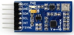
 Design with hw860 in Cirkit Designer
Introduction
The HW860 is a high-performance microcontroller designed for embedded applications. It is optimized for low power consumption, making it ideal for battery-powered devices and energy-efficient systems. With multiple I/O ports and integrated communication interfaces, the HW860 provides flexibility and scalability for a wide range of applications.
Explore Projects Built with hw860
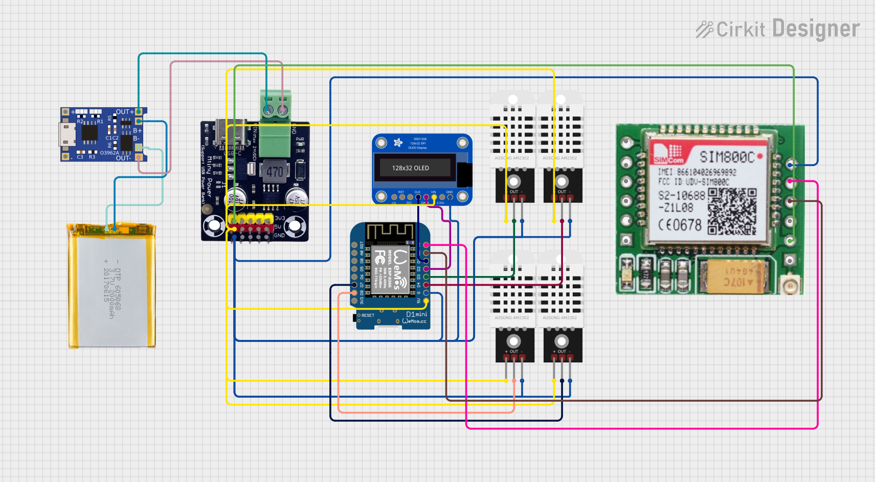 Open Project in Cirkit Designer
 Open Project in Cirkit Designer
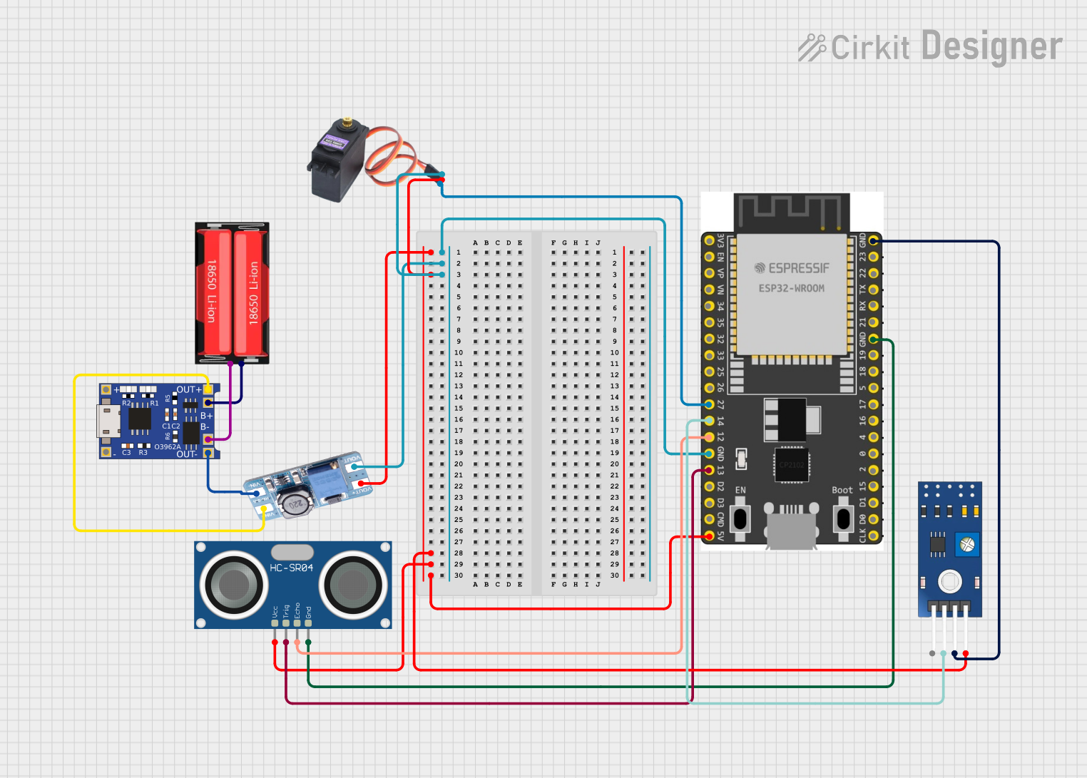 Open Project in Cirkit Designer
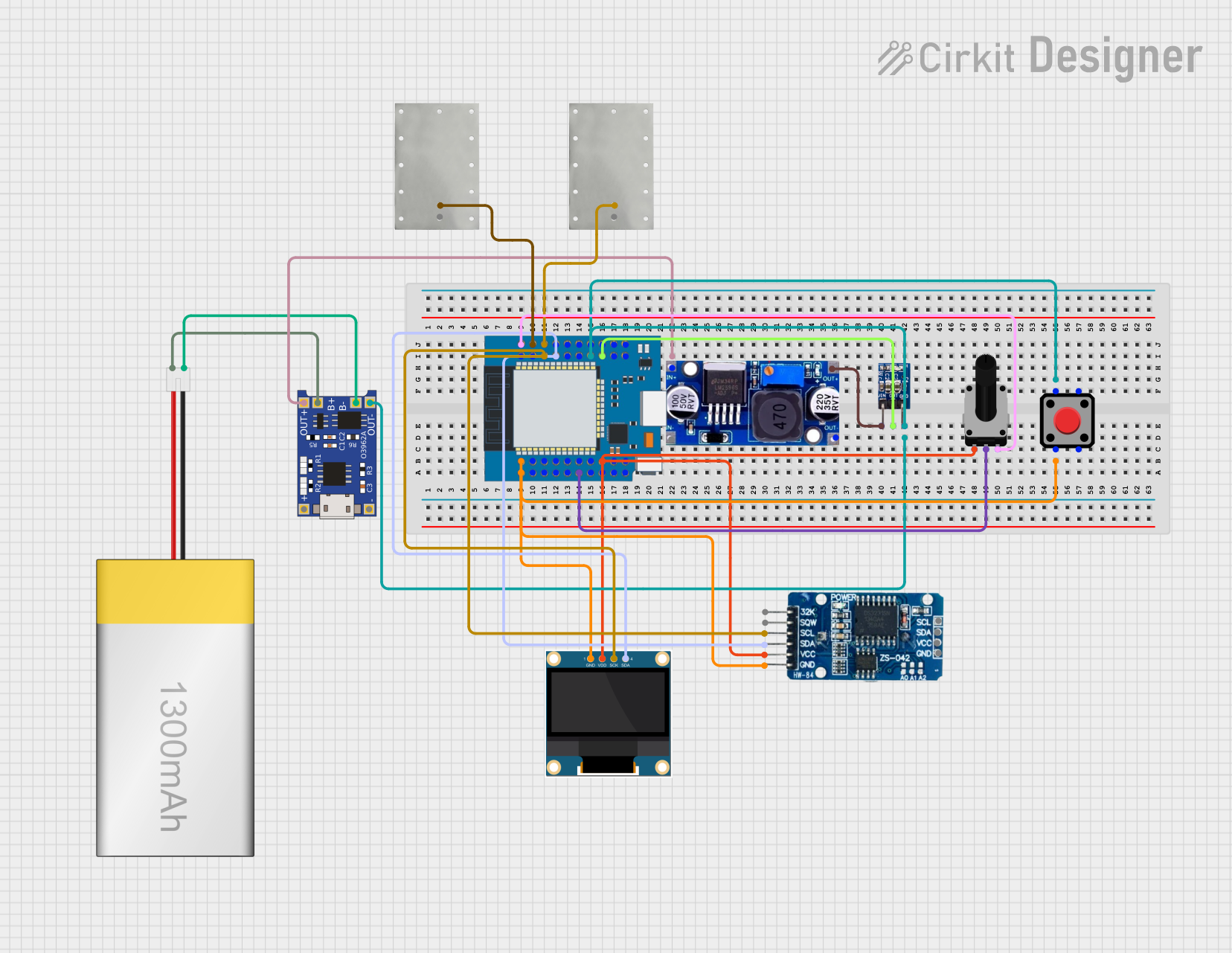 Open Project in Cirkit Designer
Explore Projects Built with hw860
Open Project in Cirkit DesignerOpen Project in Cirkit DesignerOpen Project in Cirkit DesignerOpen Project in Cirkit DesignerCommon Applications and Use Cases
- IoT devices and smart home systems
- Industrial automation and control systems
- Wearable technology
- Robotics and motor control
- Data acquisition and sensor interfacing
Technical Specifications
The HW860 microcontroller offers robust performance and versatile features. Below are its key technical specifications:
| Parameter | Value |
|---|---|
| Operating Voltage | 1.8V - 3.6V |
| Maximum Clock Frequency | 48 MHz |
| Flash Memory | 128 KB |
| SRAM | 16 KB |
| GPIO Pins | 32 |
| Communication Interfaces | UART, SPI, I2C, CAN |
| ADC Resolution | 12-bit |
| Power Consumption (Active) | 5 mA @ 3.3V, 48 MHz |
| Power Consumption (Sleep) | 1 µA |
| Operating Temperature | -40°C to 85°C |
| Package Type | QFN-48 |
Pin Configuration and Descriptions
The HW860 comes in a QFN-48 package with the following pin configuration:
| Pin Number | Pin Name | Function |
|---|---|---|
| 1 | VDD | Power Supply (1.8V - 3.6V) |
| 2 | GND | Ground |
| 3 | GPIO1 | General Purpose I/O |
| 4 | GPIO2 | General Purpose I/O |
| 5 | UART_TX | UART Transmit |
| 6 | UART_RX | UART Receive |
| 7 | SPI_MOSI | SPI Master Out Slave In |
| 8 | SPI_MISO | SPI Master In Slave Out |
| 9 | SPI_SCK | SPI Clock |
| 10 | I2C_SCL | I2C Clock Line |
| 11 | I2C_SDA | I2C Data Line |
| 12 | ADC_IN1 | Analog Input Channel 1 |
| 13 | ADC_IN2 | Analog Input Channel 2 |
| 14-48 | GPIO3-GPIO32 | General Purpose I/O |
Usage Instructions
The HW860 microcontroller is versatile and can be used in various embedded systems. Below are the steps and considerations for using it effectively:
Basic Circuit Setup
- Power Supply: Connect the VDD pin to a regulated power source (1.8V - 3.6V) and the GND pin to ground.
- Clock Configuration: Use an external crystal oscillator or the internal clock for timing. Ensure the clock frequency does not exceed 48 MHz.
- I/O Configuration: Configure the GPIO pins as input or output based on your application. Use pull-up or pull-down resistors if necessary.
- Communication Interfaces: Connect the UART, SPI, or I2C pins to the corresponding devices. Ensure proper termination and pull-up resistors for I2C lines.
Example: Interfacing HW860 with Arduino UNO
The HW860 can be connected to an Arduino UNO for communication via UART. Below is an example code snippet for sending and receiving data:
// Example: UART Communication between Arduino UNO and HW860

// Define the UART pins for HW860
#define HW860_TX_PIN 2  // Connect to HW860 UART_RX
#define HW860_RX_PIN 3  // Connect to HW860 UART_TX

#include <SoftwareSerial.h>

// Initialize SoftwareSerial for HW860 communication
SoftwareSerial hw860Serial(HW860_RX_PIN, HW860_TX_PIN);

void setup() {
  // Start the serial communication with HW860
  hw860Serial.begin(9600); // Set baud rate to 9600
  Serial.begin(9600);      // Start Serial Monitor for debugging

  Serial.println("Arduino is ready to communicate with HW860.");
}

void loop() {
  // Send data to HW860
  hw860Serial.println("Hello HW860!");

  // Check if HW860 has sent data
  if (hw860Serial.available()) {
    String receivedData = hw860Serial.readString();
    Serial.print("Data from HW860: ");
    Serial.println(receivedData);
  }

  delay(1000); // Wait for 1 second
}
Important Considerations
- Voltage Levels: Ensure the voltage levels of the HW860 and connected devices are compatible. Use level shifters if necessary.
- Decoupling Capacitors: Place decoupling capacitors (e.g., 0.1 µF) near the VDD pin to stabilize the power supply.
- Programming Interface: Use a compatible programmer or bootloader to upload firmware to the HW860.
- ESD Protection: Implement ESD protection on exposed pins to prevent damage.
Troubleshooting and FAQs
Common Issues and Solutions
Microcontroller Not Powering On
- Cause: Incorrect power supply voltage or missing ground connection.
- Solution: Verify the VDD and GND connections. Ensure the supply voltage is within the 1.8V - 3.6V range.
Communication Failure
- Cause: Incorrect baud rate or wiring.
- Solution: Double-check the baud rate settings and ensure proper connections for UART, SPI, or I2C.
GPIO Pins Not Responding
- Cause: Incorrect pin configuration or missing pull-up/pull-down resistors.
- Solution: Verify the pin mode (input/output) and add pull-up or pull-down resistors if required.
High Power Consumption
- Cause: Microcontroller not entering sleep mode.
- Solution: Implement power-saving features in the firmware and ensure unused peripherals are disabled.
FAQs
Q1: Can the HW860 operate at 5V?
No, the HW860 operates within a voltage range of 1.8V to 3.6V. Exceeding this range may damage the microcontroller.
Q2: How do I program the HW860?
The HW860 can be programmed using a compatible programmer or bootloader. Refer to the manufacturer's documentation for detailed instructions.
Q3: What is the maximum ADC sampling rate?
The HW860's ADC supports a maximum sampling rate of 1 MSPS (Mega Samples Per Second).
Q4: Can I use all GPIO pins simultaneously?
Yes, all 32 GPIO pins can be used simultaneously, but ensure the total current draw does not exceed the microcontroller's limits.
Q5: Does the HW860 support wireless communication?
No, the HW860 does not have built-in wireless communication. However, it can interface with external wireless modules via UART, SPI, or I2C.
This concludes the HW860 documentation. For further assistance, refer to the manufacturer's datasheet or contact technical support.