How to Use DC Circuit breaker: Examples, Pinouts, and Specs
Introduction
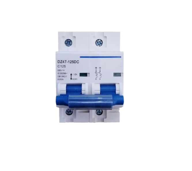
A DC circuit breaker is a protective device designed to automatically interrupt the flow of direct current (DC) in a circuit when an overload or short circuit occurs. It ensures the safety of electrical systems by preventing damage to components and reducing the risk of fire or other hazards caused by excessive current. Unlike fuses, which need to be replaced after tripping, DC circuit breakers can be reset and reused.
Explore Projects Built with DC Circuit breaker
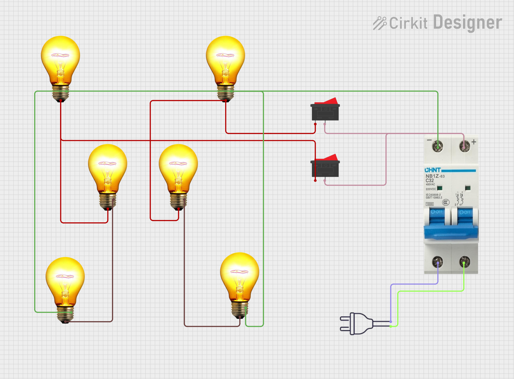

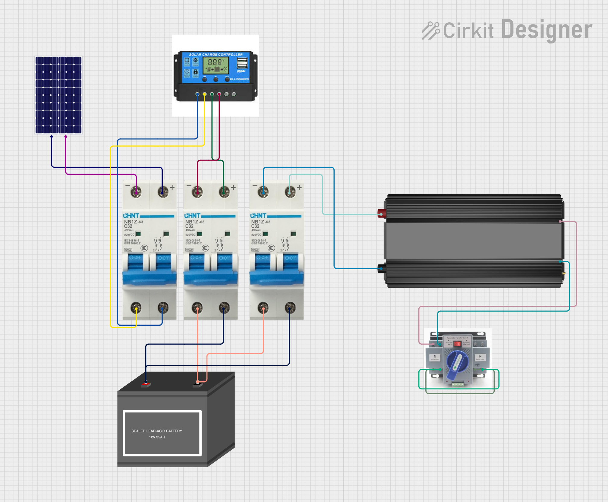
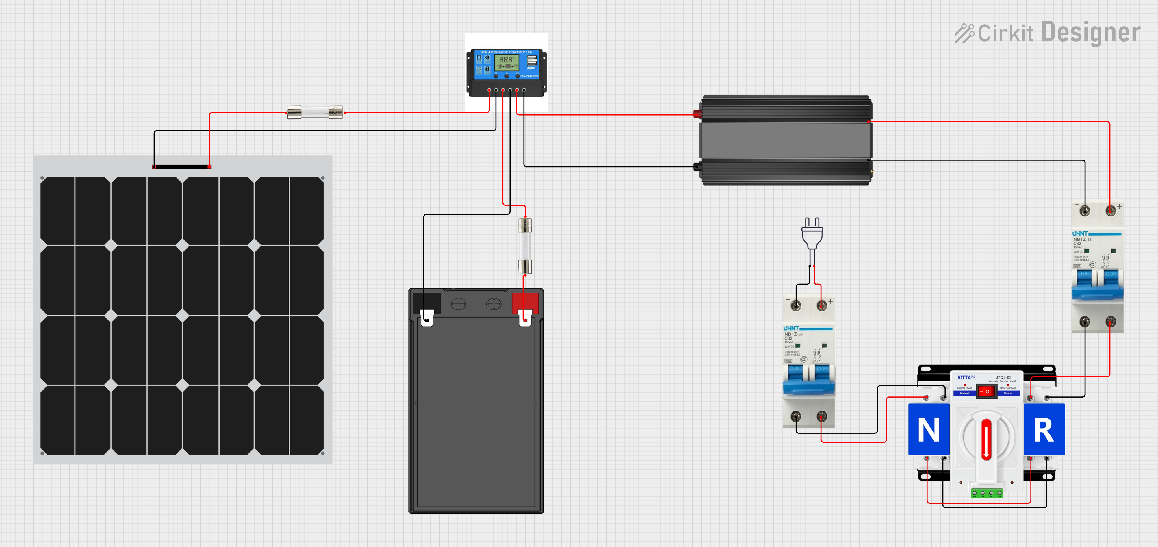
Explore Projects Built with DC Circuit breaker
Common Applications and Use Cases
- Solar power systems to protect photovoltaic (PV) panels and inverters.
- Electric vehicles (EVs) to safeguard battery packs and motor controllers.
- Industrial DC power supplies and distribution systems.
- Telecommunications equipment to protect sensitive electronics.
- Battery banks in renewable energy storage systems.
Technical Specifications
Below are the general technical specifications for a typical DC circuit breaker. Always refer to the datasheet of the specific model you are using for precise details.
| Parameter | Specification |
|---|---|
| Rated Voltage | 12V, 24V, 48V, 100V, or higher (varies) |
| Rated Current | 1A to 250A (depending on model) |
| Breaking Capacity | 6kA to 10kA (varies by model) |
| Trip Mechanism | Thermal, Magnetic, or Thermal-Magnetic |
| Operating Temperature | -20°C to 70°C |
| Reset Type | Manual reset or automatic reset |
| Mounting Style | DIN rail or panel-mounted |
| Poles | Single-pole, double-pole, or multi-pole |
Pin Configuration and Descriptions
DC circuit breakers typically have terminals for input and output connections. Below is a general description of the terminal configuration:
| Terminal | Description |
|---|---|
| Line (Input) | Connects to the positive terminal of the DC power source. |
| Load (Output) | Connects to the positive terminal of the load. |
| Ground (Optional) | Some models include a ground terminal for safety. |
Usage Instructions
How to Use the Component in a Circuit
- Determine the Ratings: Select a DC circuit breaker with a voltage and current rating suitable for your circuit. Ensure the breaking capacity exceeds the maximum fault current of your system.
- Connect the Input: Attach the positive terminal of the DC power source to the "Line" or input terminal of the circuit breaker.
- Connect the Output: Connect the "Load" or output terminal of the circuit breaker to the positive terminal of the load.
- Secure the Ground (if applicable): If the circuit breaker includes a ground terminal, connect it to the system ground for added safety.
- Test the Circuit: Power on the system and verify that the circuit breaker operates correctly under normal conditions. Test the tripping mechanism by simulating an overload or short circuit.
Important Considerations and Best Practices
- Polarity: DC circuit breakers are polarity-sensitive. Ensure correct polarity when connecting the input and output terminals.
- Breaking Capacity: Verify that the circuit breaker can handle the maximum fault current of your system.
- Resetting: After a trip, inspect the circuit for faults before resetting the breaker.
- Mounting: Use appropriate mounting hardware (e.g., DIN rail or panel mount) to secure the circuit breaker in place.
- Environmental Conditions: Avoid exposing the circuit breaker to extreme temperatures, moisture, or dust.
Example: Using a DC Circuit Breaker with an Arduino UNO
While DC circuit breakers are not directly interfaced with microcontrollers like the Arduino UNO, they can be used to protect the power supply to the Arduino. Below is an example of how to integrate a DC circuit breaker into a simple Arduino-powered circuit:
Circuit Description
- A 12V DC power supply is connected to a DC circuit breaker.
- The output of the circuit breaker powers the Arduino UNO and a connected load (e.g., an LED).
Code Example
// Example Arduino code to control an LED
// This assumes the circuit breaker is protecting the power supply to the Arduino.

const int ledPin = 13; // Pin connected to the LED

void setup() {
  pinMode(ledPin, OUTPUT); // Set the LED pin as an output
}

void loop() {
  digitalWrite(ledPin, HIGH); // Turn the LED on
  delay(1000);                // Wait for 1 second
  digitalWrite(ledPin, LOW);  // Turn the LED off
  delay(1000);                // Wait for 1 second
}

// Note: The DC circuit breaker is not controlled by the Arduino.
// It is used to protect the power supply and the Arduino from overcurrent.
Troubleshooting and FAQs
Common Issues and Solutions
| Issue | Solution |
|---|---|
| Circuit breaker trips frequently | Check for overloads or short circuits in the connected load. Reduce the load if necessary. |
| Circuit breaker does not trip during a fault | Verify that the breaker is rated for the correct voltage and current. Replace if faulty. |
| Circuit breaker does not reset | Ensure the fault condition has been resolved before attempting to reset. |
| Overheating of the circuit breaker | Check for loose connections or excessive current. Tighten connections and ensure proper ratings. |
FAQs
Can I use an AC circuit breaker in a DC circuit?
- No, AC and DC circuit breakers are designed differently. Always use a DC circuit breaker for DC circuits.
How do I choose the right DC circuit breaker?
- Select a breaker with a voltage and current rating that matches your circuit. Ensure the breaking capacity is sufficient for the maximum fault current.
What happens if I connect the circuit breaker with reversed polarity?
- Reversed polarity can damage the circuit breaker or cause it to malfunction. Always double-check the connections.
Can a DC circuit breaker protect against both overloads and short circuits?
- Yes, most DC circuit breakers are designed to protect against both conditions.
By following this documentation, you can safely and effectively use a DC circuit breaker in your projects.