How to Use QTRX-MD-16A Reflectance Sensor Array: Examples, Pinouts, and Specs
Introduction
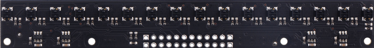
The QTRX-MD-16A Reflectance Sensor Array, manufactured by Pololu, is a high-performance sensor array designed for detecting surface reflectance. It is commonly used in robotics applications such as line-following robots, edge detection, and obstacle avoidance. The array consists of 16 pairs of infrared emitters and photodetectors, enabling precise and high-resolution surface reflectance measurements. Its compact design and modularity make it suitable for a wide range of projects.
Explore Projects Built with QTRX-MD-16A Reflectance Sensor Array
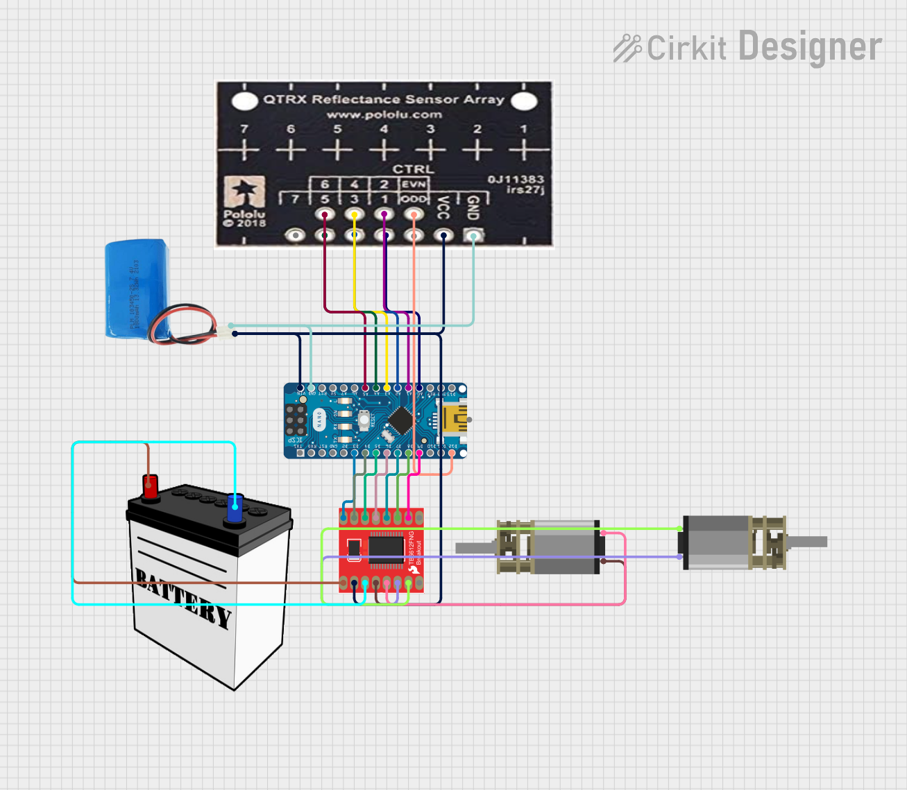
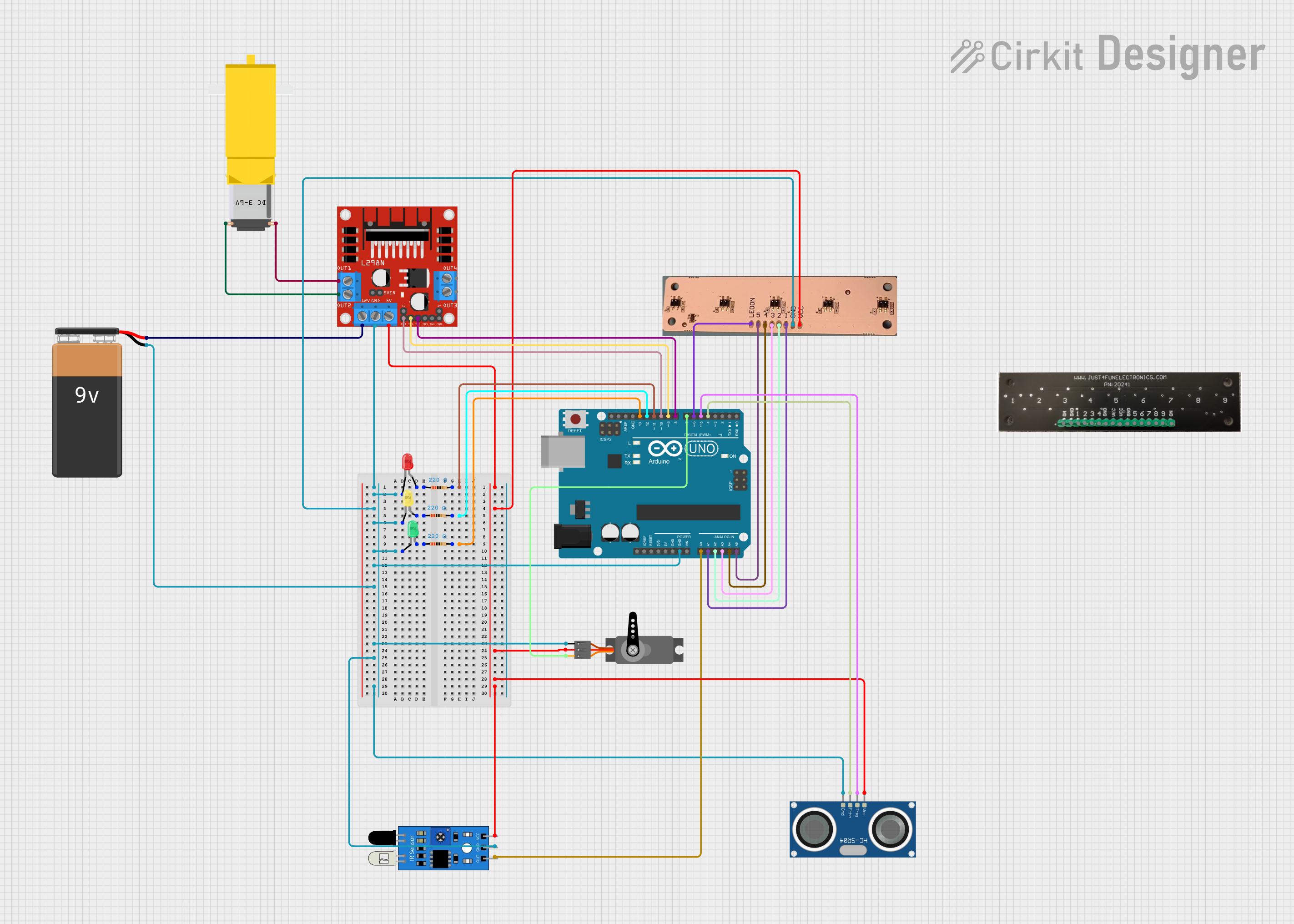
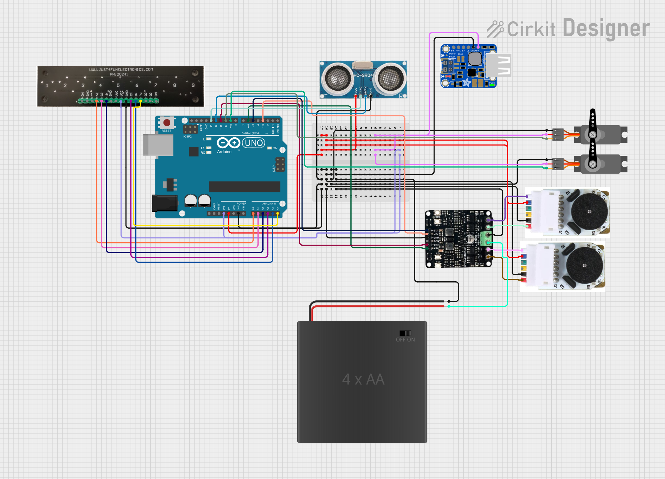

Explore Projects Built with QTRX-MD-16A Reflectance Sensor Array
Common Applications
- Line-following robots
- Edge detection in autonomous vehicles
- Obstacle detection and avoidance
- Surface reflectance measurement for industrial automation
- Maze-solving robots
Technical Specifications
The following table outlines the key technical details of the QTRX-MD-16A Reflectance Sensor Array:
| Parameter | Value |
|---|---|
| Manufacturer | Pololu |
| Part Number | QTRX-MD-16A |
| Operating Voltage | 2.9 V to 5.5 V |
| Current Consumption | ~100 mA (typical, all emitters on) |
| Number of Sensors | 16 |
| Sensor Type | Infrared emitter and phototransistor pair |
| Output Type | Analog voltage (0 V to Vcc) |
| Dimensions | 145 mm × 15 mm × 3 mm |
| Weight | 7.5 g |
| Optimal Sensing Distance | 3 mm to 9 mm |
| Operating Temperature | -40°C to 85°C |
Pin Configuration and Descriptions
The QTRX-MD-16A has a 16-pin interface for sensor outputs and additional pins for power and control. The pin configuration is as follows:
| Pin | Name | Description |
|---|---|---|
| 1-16 | OUT1-OUT16 | Analog output for each sensor, corresponding to the reflectance detected. |
| 17 | VCC | Power supply input (2.9 V to 5.5 V). |
| 18 | GND | Ground connection. |
| 19 | LEDON | Control pin for enabling/disabling the IR emitters. High = ON, Low = OFF. |
Usage Instructions
How to Use the QTRX-MD-16A in a Circuit
- Power the Sensor Array: Connect the VCC pin to a regulated power supply (2.9 V to 5.5 V) and the GND pin to the ground of your circuit.
- Connect Outputs: Each sensor output (OUT1 to OUT16) provides an analog voltage proportional to the reflectance detected. Connect these outputs to the analog input pins of a microcontroller or ADC (Analog-to-Digital Converter).
- Enable Emitters: Use the LEDON pin to control the IR emitters. Set the pin HIGH to enable the emitters or LOW to disable them.
- Read Sensor Data: Measure the analog voltage from each output pin. A higher voltage indicates higher reflectance (lighter surfaces), while a lower voltage indicates lower reflectance (darker surfaces).
Important Considerations and Best Practices
- Optimal Sensing Distance: For best results, position the sensor array 3 mm to 9 mm above the surface being measured.
- Emitter Control: To save power, disable the emitters (set LEDON to LOW) when the sensor is not in use.
- Calibration: Calibrate the sensor array for your specific application to account for variations in surface reflectance and ambient lighting.
- Avoid Interference: Ensure that the sensor array is not exposed to direct sunlight or other strong IR sources, as this may affect accuracy.
Example: Using QTRX-MD-16A with Arduino UNO
Below is an example of how to use the QTRX-MD-16A with an Arduino UNO to read reflectance values from the first sensor (OUT1):
// Define the pin connections
#define SENSOR_PIN A0  // Connect OUT1 to Arduino analog pin A0
#define LEDON_PIN 7    // Connect LEDON to Arduino digital pin 7

void setup() {
  pinMode(LEDON_PIN, OUTPUT);  // Set LEDON pin as output
  digitalWrite(LEDON_PIN, HIGH);  // Turn on the IR emitters
  Serial.begin(9600);  // Initialize serial communication
}

void loop() {
  int sensorValue = analogRead(SENSOR_PIN);  // Read the analog value from OUT1
  Serial.print("Sensor Value: ");
  Serial.println(sensorValue);  // Print the sensor value to the Serial Monitor
  delay(100);  // Wait for 100 ms before the next reading
}
Troubleshooting and FAQs
Common Issues and Solutions
No Output from Sensors
- Cause: The IR emitters may be disabled.
- Solution: Ensure the LEDON pin is set HIGH to enable the emitters.
Inconsistent Readings
- Cause: The sensor array may be too far from or too close to the surface.
- Solution: Adjust the distance to fall within the optimal range of 3 mm to 9 mm.
Interference from Ambient Light
- Cause: Strong ambient light or IR sources may interfere with the sensors.
- Solution: Use the sensor in a controlled lighting environment or shield it from external IR sources.
High Power Consumption
- Cause: All emitters are enabled continuously.
- Solution: Disable the emitters (set LEDON to LOW) when the sensor is not actively measuring.
FAQs
Q: Can the QTRX-MD-16A be used with a 3.3 V microcontroller?
A: Yes, the sensor array operates within a voltage range of 2.9 V to 5.5 V, making it compatible with 3.3 V systems.
Q: How do I calibrate the sensor array?
A: Calibration involves reading the sensor outputs for both the darkest and lightest surfaces in your application and mapping the values to a desired range (e.g., 0 to 100).
Q: Can I use fewer than 16 sensors?
A: Yes, you can use only the outputs you need. Unused outputs can be left unconnected.
Q: What is the maximum sampling rate?
A: The sampling rate depends on your microcontroller's ADC speed. Most microcontrollers can sample each sensor at several kHz.