How to Use FT232RL Module: Examples, Pinouts, and Specs
Introduction
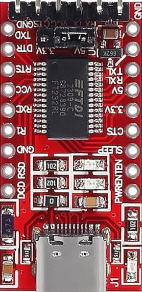
The FT232RL is a USB to serial UART interface module, designed to bridge communication between a USB port and serial devices. It is based on the FT232RL chip from FTDI, which is widely recognized for its reliability and ease of use. This module is commonly used in microcontroller projects, such as Arduino-based systems, to enable USB connectivity for programming, debugging, or data transfer.
Explore Projects Built with FT232RL Module


Explore Projects Built with FT232RL Module
Common Applications and Use Cases
- Programming microcontrollers (e.g., Arduino, ESP8266, ESP32)
- Debugging serial communication in embedded systems
- USB-to-TTL conversion for legacy serial devices
- Data logging and communication with sensors or other peripherals
- Prototyping and testing serial communication protocols
Technical Specifications
The FT232RL module has the following key technical details:
| Parameter | Value |
|---|---|
| USB Standard | USB 2.0 Full Speed |
| UART Baud Rate | 300 bps to 3 Mbps |
| Operating Voltage | 3.3V or 5V (selectable via jumper) |
| Logic Level | 3.3V or 5V (selectable via jumper) |
| Power Supply | USB-powered |
| Driver Support | Windows, macOS, Linux |
| Operating Temperature | -40°C to +85°C |
Pin Configuration and Descriptions
The FT232RL module typically includes the following pins:
| Pin Name | Description |
|---|---|
| GND | Ground connection |
| VCC | Power input/output (3.3V or 5V, depending on jumper setting) |
| TXD | Transmit data (UART output) |
| RXD | Receive data (UART input) |
| DTR | Data Terminal Ready (used for auto-reset in microcontroller programming) |
| CTS | Clear to Send (flow control, optional) |
| RTS | Request to Send (flow control, optional) |
| 3V3 | 3.3V output (can power external devices) |
Usage Instructions
How to Use the FT232RL Module in a Circuit
Connect the Module to Your Device:
- Connect the
TXDpin of the FT232RL module to theRXpin of your microcontroller or serial device. - Connect the
RXDpin of the FT232RL module to theTXpin of your microcontroller or serial device. - Connect the
GNDpin to the ground of your circuit. - If your device requires power, connect the
VCCpin to the appropriate voltage (3.3V or 5V).
- Connect the
Install Drivers:
- Download and install the FTDI drivers from the official FTDI website (https://ftdichip.com/).
- Ensure the drivers are properly installed on your operating system.
Connect to a USB Port:
- Plug the FT232RL module into a USB port on your computer using a USB cable.
- Verify that the module is recognized as a COM port in your operating system.
Test Communication:
- Use a serial terminal program (e.g., PuTTY, Tera Term, or Arduino Serial Monitor) to test communication.
- Set the baud rate and other serial parameters to match your device's configuration.
Important Considerations and Best Practices
- Voltage Selection: Ensure the voltage jumper is set correctly (3.3V or 5V) to match your device's requirements.
- Avoid Overloading: Do not draw excessive current from the
VCCor3V3pins, as the module is USB-powered. - Static Protection: Handle the module carefully to avoid damage from electrostatic discharge (ESD).
- Auto-Reset Feature: If programming an Arduino, connect the
DTRpin to theRESETpin of the Arduino through a 0.1 µF capacitor to enable auto-reset functionality.
Example: Using FT232RL with Arduino UNO
Below is an example of how to use the FT232RL module to upload code to an Arduino UNO:
Connect the FT232RL module to the Arduino UNO as follows:
TXD→RX(Pin 0 on Arduino)RXD→TX(Pin 1 on Arduino)GND→GNDDTR→RESET(via a 0.1 µF capacitor)
Open the Arduino IDE and select the correct COM port for the FT232RL module.
Upload your sketch to the Arduino UNO.
// Example Arduino Sketch: Blink an LED
// This sketch blinks the built-in LED on pin 13 of the Arduino UNO.

void setup() {
  pinMode(13, OUTPUT); // Set pin 13 as an output
}

void loop() {
  digitalWrite(13, HIGH); // Turn the LED on
  delay(1000);            // Wait for 1 second
  digitalWrite(13, LOW);  // Turn the LED off
  delay(1000);            // Wait for 1 second
}
Troubleshooting and FAQs
Common Issues and Solutions
Module Not Recognized by Computer:
- Ensure the USB cable is functional and properly connected.
- Verify that the FTDI drivers are installed correctly.
- Try a different USB port or computer.
No Communication with Device:
- Double-check the
TXDandRXDconnections (they must be crossed:TXDtoRX,RXDtoTX). - Ensure the baud rate and serial settings match the device's configuration.
- Double-check the
Device Not Powering On:
- Verify the voltage jumper setting (3.3V or 5V) matches your device's requirements.
- Check the USB port for sufficient power output.
Auto-Reset Not Working:
- Ensure the
DTRpin is connected to theRESETpin of the microcontroller via a 0.1 µF capacitor.
- Ensure the
FAQs
Q: Can the FT232RL module be used with 1.8V logic devices?
A: No, the FT232RL module supports 3.3V and 5V logic levels only. For 1.8V devices, a level shifter is required.
Q: How do I check the COM port assigned to the FT232RL module?
A: On Windows, open "Device Manager" and look under "Ports (COM & LPT)". On macOS or Linux, use the ls /dev/tty* command to find the device.
Q: Is the FT232RL module compatible with all operating systems?
A: Yes, the module is compatible with Windows, macOS, and Linux, provided the appropriate drivers are installed.
Q: Can I use the FT232RL module for SPI or I2C communication?
A: No, the FT232RL module is designed for UART (serial) communication only. For SPI or I2C, consider using other dedicated modules or chips.
By following this documentation, you can effectively use the FT232RL module in your projects and troubleshoot common issues with ease.