Cirkit Designer Logo
Cirkit Designer
Your all-in-one circuit design IDE
Home / 
Component Documentation

How to Use MMA7361: Examples, Pinouts, and Specs

Image of MMA7361
Cirkit Designer LogoDesign with MMA7361 in Cirkit Designer

Introduction

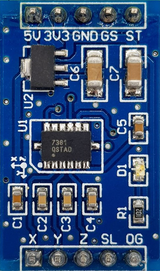
The MMA7361 is a low power, low profile capacitive micro-machined accelerometer. It features signal conditioning, a 1-pole low pass filter, temperature compensation, self-test, and g-Select which allows for the selection between two sensitivities. This versatile component is widely used in various applications such as motion sensing, tilt detection, and vibration monitoring.

Explore Projects Built with MMA7361

Use Cirkit Designer to design, explore, and prototype these projects online. Some projects support real-time simulation. Click "Open Project" to start designing instantly!
Arduino Mega 2560 Based Security System with Fingerprint Authentication and SMS Alerts
Image of Door security system: A project utilizing MMA7361 in a practical application
This circuit features an Arduino Mega 2560 microcontroller interfaced with a SIM800L GSM module, two fingerprint scanners, an I2C LCD display, an IR sensor, and a piezo buzzer. Power management is handled by a PowerBoost 1000 Basic Pad USB, a TP4056 charging module, and a Li-ion 18650 battery, with an option to use a Mini AC-DC 110V-230V to 5V 700mA module for direct power supply. The primary functionality appears to be a security system with GSM communication capabilities, biometric access control, and visual/audible feedback.
Cirkit Designer LogoOpen Project in Cirkit Designer
Battery-Powered Emergency Alert System with NUCLEO-F072RB, SIM800L, and GPS NEO 6M
Image of women safety: A project utilizing MMA7361 in a practical application
This circuit is an emergency alert system that uses a NUCLEO-F072RB microcontroller to send SMS alerts and make calls via a SIM800L GSM module, while obtaining location data from a GPS NEO 6M module. The system is powered by a Li-ion battery and includes a TP4056 module for battery charging and protection, with a rocker switch to control power to the microcontroller.
Cirkit Designer LogoOpen Project in Cirkit Designer
Logic Gate Circuit with 7408 AND and 7432 OR ICs
Image of gate: A project utilizing MMA7361 in a practical application
This circuit includes a 7408 AND gate IC and a 7432 OR gate IC, both powered by a common VCC and GND connection. The circuit is designed to perform basic logical operations, combining AND and OR gates for digital signal processing.
Cirkit Designer LogoOpen Project in Cirkit Designer
Cellular-Enabled IoT Device with Real-Time Clock and Power Management
Image of LRCM PHASE 2 BASIC: A project utilizing MMA7361 in a practical application
This circuit features a LilyGo-SIM7000G module for cellular communication and GPS functionality, interfaced with an RTC DS3231 for real-time clock capabilities. It includes voltage sensing through two voltage sensor modules, and uses an 8-channel opto-coupler for isolating different parts of the circuit. Power management is handled by a buck converter connected to a DC power source and batteries, with a fuse for protection and a rocker switch for on/off control. Additionally, there's an LED for indication purposes.
Cirkit Designer LogoOpen Project in Cirkit Designer

Explore Projects Built with MMA7361

Use Cirkit Designer to design, explore, and prototype these projects online. Some projects support real-time simulation. Click "Open Project" to start designing instantly!
Image of Door security system: A project utilizing MMA7361 in a practical application
Arduino Mega 2560 Based Security System with Fingerprint Authentication and SMS Alerts
This circuit features an Arduino Mega 2560 microcontroller interfaced with a SIM800L GSM module, two fingerprint scanners, an I2C LCD display, an IR sensor, and a piezo buzzer. Power management is handled by a PowerBoost 1000 Basic Pad USB, a TP4056 charging module, and a Li-ion 18650 battery, with an option to use a Mini AC-DC 110V-230V to 5V 700mA module for direct power supply. The primary functionality appears to be a security system with GSM communication capabilities, biometric access control, and visual/audible feedback.
Cirkit Designer LogoOpen Project in Cirkit Designer
Image of women safety: A project utilizing MMA7361 in a practical application
Battery-Powered Emergency Alert System with NUCLEO-F072RB, SIM800L, and GPS NEO 6M
This circuit is an emergency alert system that uses a NUCLEO-F072RB microcontroller to send SMS alerts and make calls via a SIM800L GSM module, while obtaining location data from a GPS NEO 6M module. The system is powered by a Li-ion battery and includes a TP4056 module for battery charging and protection, with a rocker switch to control power to the microcontroller.
Cirkit Designer LogoOpen Project in Cirkit Designer
Image of gate: A project utilizing MMA7361 in a practical application
Logic Gate Circuit with 7408 AND and 7432 OR ICs
This circuit includes a 7408 AND gate IC and a 7432 OR gate IC, both powered by a common VCC and GND connection. The circuit is designed to perform basic logical operations, combining AND and OR gates for digital signal processing.
Cirkit Designer LogoOpen Project in Cirkit Designer
Image of LRCM PHASE 2 BASIC: A project utilizing MMA7361 in a practical application
Cellular-Enabled IoT Device with Real-Time Clock and Power Management
This circuit features a LilyGo-SIM7000G module for cellular communication and GPS functionality, interfaced with an RTC DS3231 for real-time clock capabilities. It includes voltage sensing through two voltage sensor modules, and uses an 8-channel opto-coupler for isolating different parts of the circuit. Power management is handled by a buck converter connected to a DC power source and batteries, with a fuse for protection and a rocker switch for on/off control. Additionally, there's an LED for indication purposes.
Cirkit Designer LogoOpen Project in Cirkit Designer

Common Applications

  • Mobile devices for screen orientation
  • Gaming controllers for motion detection
  • Robotics for balance and movement control
  • Automotive systems for crash detection and airbag deployment
  • Industrial equipment for vibration monitoring

Technical Specifications

Key Technical Details

Parameter Value
Supply Voltage (Vdd) 2.2V to 3.6V
Supply Current 400 µA
Sleep Mode Current 3 µA
Sensitivity (Selectable) 800 mV/g (±1.5g), 206 mV/g (±6g)
Output Signal Analog
Bandwidth 400 Hz
Operating Temperature -40°C to +85°C

Pin Configuration and Descriptions

Pin Name Description
1 Vdd Power Supply (2.2V to 3.6V)
2 GND Ground
3 Xout X-axis Analog Output
4 Yout Y-axis Analog Output
5 Zout Z-axis Analog Output
6 ST Self-Test (Active High)
7 G-Select Sensitivity Selection (High: ±6g, Low: ±1.5g)
8 Sleep Sleep Mode (Active High)

Usage Instructions

How to Use the Component in a Circuit

  1. Power Supply: Connect the Vdd pin to a 3.3V power supply and the GND pin to the ground.
  2. Analog Outputs: Connect the Xout, Yout, and Zout pins to the analog input pins of a microcontroller (e.g., Arduino).
  3. Sensitivity Selection: Use the G-Select pin to choose the sensitivity. Connect it to GND for ±1.5g or to Vdd for ±6g.
  4. Self-Test: To perform a self-test, set the ST pin high. This will apply a known force to the sensor to verify its operation.
  5. Sleep Mode: To reduce power consumption, set the Sleep pin high to put the device into sleep mode.

Important Considerations and Best Practices

  • Decoupling Capacitor: Place a 0.1 µF capacitor close to the Vdd pin to filter out noise.
  • Mounting: Ensure the accelerometer is mounted securely to avoid false readings due to vibrations.
  • Calibration: Calibrate the sensor in a known orientation to ensure accurate readings.
  • Temperature Effects: Be aware of temperature variations and their potential impact on sensor readings.

Example Circuit with Arduino UNO

// MMA7361 Accelerometer with Arduino UNO
// Connections:
// MMA7361 Vdd -> 3.3V
// MMA7361 GND -> GND
// MMA7361 Xout -> A0
// MMA7361 Yout -> A1
// MMA7361 Zout -> A2
// MMA7361 G-Select -> GND (for ±1.5g sensitivity)

const int xPin = A0; // X-axis output
const int yPin = A1; // Y-axis output
const int zPin = A2; // Z-axis output

void setup() {
  Serial.begin(9600); // Initialize serial communication
}

void loop() {
  int xValue = analogRead(xPin); // Read X-axis value
  int yValue = analogRead(yPin); // Read Y-axis value
  int zValue = analogRead(zPin); // Read Z-axis value

  // Convert analog values to g-force
  float xG = (xValue - 512) * (3.3 / 1024) / 0.8;
  float yG = (yValue - 512) * (3.3 / 1024) / 0.8;
  float zG = (zValue - 512) * (3.3 / 1024) / 0.8;

  // Print values to serial monitor
  Serial.print("X: ");
  Serial.print(xG);
  Serial.print(" g, Y: ");
  Serial.print(yG);
  Serial.print(" g, Z: ");
  Serial.print(zG);
  Serial.println(" g");

  delay(500); // Wait for 500 milliseconds
}

Troubleshooting and FAQs

Common Issues and Solutions

  1. No Output Signal

    • Solution: Check the power supply connections. Ensure Vdd is connected to 3.3V and GND to ground.
  2. Inaccurate Readings

    • Solution: Calibrate the sensor. Ensure the sensor is mounted securely and not subject to external vibrations.
  3. High Power Consumption

    • Solution: Use the Sleep mode by setting the Sleep pin high when the sensor is not in use.
  4. Self-Test Fails

    • Solution: Verify the ST pin connection. Ensure it is set high during the self-test procedure.

FAQs

Q1: Can I use the MMA7361 with a 5V microcontroller?

  • A1: Yes, but you need to use a voltage regulator to step down the 5V to 3.3V for the MMA7361.

Q2: How do I change the sensitivity of the MMA7361?

  • A2: Use the G-Select pin. Connect it to GND for ±1.5g sensitivity or to Vdd for ±6g sensitivity.

Q3: What is the purpose of the self-test feature?

  • A3: The self-test feature applies a known force to the sensor to verify its operation and ensure it is functioning correctly.

Q4: How do I reduce noise in the sensor readings?

  • A4: Use a decoupling capacitor (0.1 µF) close to the Vdd pin and ensure proper grounding. Additionally, you can implement software filtering techniques.

This documentation provides a comprehensive guide to using the MMA7361 accelerometer. Whether you are a beginner or an experienced user, following these instructions and best practices will help you effectively integrate this component into your projects.