How to Use JX-4615N-A3 BATTERY INDICATOR : Examples, Pinouts, and Specs
Introduction
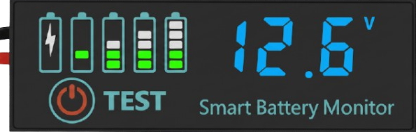
The JX-4615N-A3 Battery Indicator is a compact and efficient module designed to provide visual feedback on the charge level of a battery. It uses a series of LED lights to indicate whether the battery is full, low, or empty, making it an essential tool for monitoring battery health in various applications. This component is widely used in portable electronics, power banks, electric vehicles, and solar energy systems.
Explore Projects Built with JX-4615N-A3 BATTERY INDICATOR


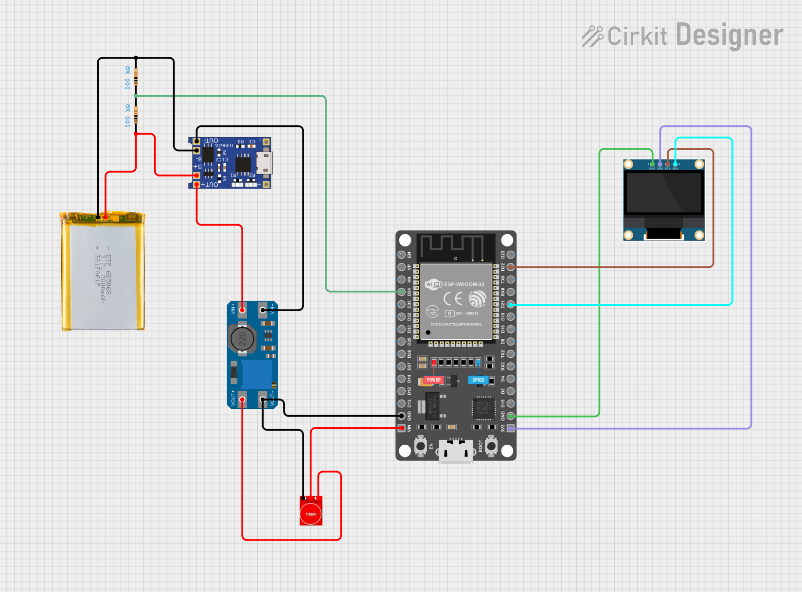
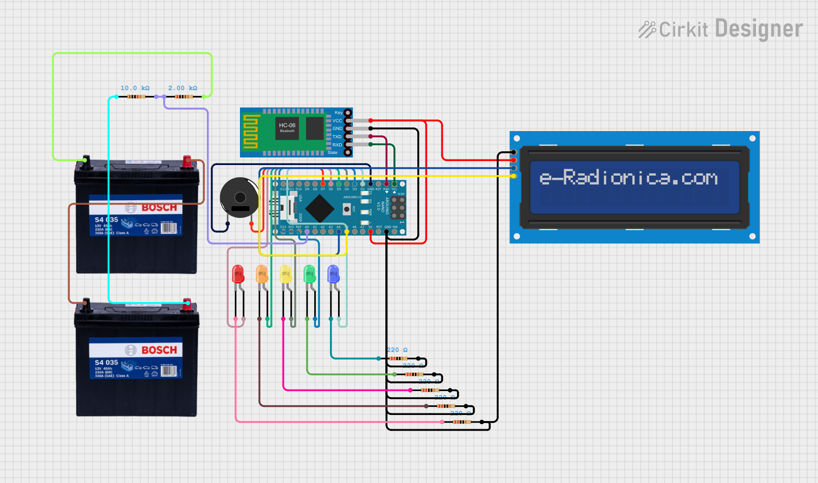
Explore Projects Built with JX-4615N-A3 BATTERY INDICATOR
Common Applications and Use Cases
- Monitoring battery levels in portable devices
- Power banks and charging stations
- Electric vehicles and scooters
- Solar-powered systems
- DIY electronics projects
Technical Specifications
The following table outlines the key technical details of the JX-4615N-A3 Battery Indicator:
| Parameter | Value |
|---|---|
| Operating Voltage | 3.7V to 12V DC |
| Operating Current | ≤ 20mA |
| Battery Type Supported | Lithium-ion, Lead-acid |
| LED Indicators | 3 LEDs (Full, Medium, Low) |
| Dimensions | 25mm x 15mm x 5mm |
| Operating Temperature | -20°C to 70°C |
| Mounting Type | PCB Mount or Panel Mount |
Pin Configuration and Descriptions
The JX-4615N-A3 has a simple pinout for easy integration into circuits. The pin configuration is as follows:
| Pin | Name | Description |
|---|---|---|
| 1 | VCC | Positive power supply input (3.7V to 12V DC) |
| 2 | GND | Ground connection |
| 3 | BAT+ | Positive terminal of the battery to be monitored |
| 4 | BAT- | Negative terminal of the battery to be monitored |
Usage Instructions
How to Use the Component in a Circuit
- Power Supply: Connect the VCC pin to a DC power source within the operating voltage range (3.7V to 12V). Connect the GND pin to the ground of the power source.
- Battery Connection: Attach the positive terminal of the battery to the BAT+ pin and the negative terminal to the BAT- pin.
- LED Indicators: Observe the LED lights:
- Full LED: Lights up when the battery is fully charged.
- Medium LED: Lights up when the battery is partially charged.
- Low LED: Lights up when the battery is nearly empty.
Important Considerations and Best Practices
- Ensure the operating voltage does not exceed 12V to avoid damaging the module.
- Use appropriate connectors or soldering techniques to secure the connections.
- Avoid reverse polarity connections, as this may damage the component.
- If using the module in a high-vibration environment, consider securing it with screws or adhesive.
Example: Connecting to an Arduino UNO
The JX-4615N-A3 can be used with an Arduino UNO to monitor battery levels and trigger actions based on the charge state. Below is an example code snippet:
// Example code for using JX-4615N-A3 with Arduino UNO
// This code reads the battery level and prints the status to the Serial Monitor.

const int fullLED = 2;  // Pin connected to the Full LED
const int mediumLED = 3;  // Pin connected to the Medium LED
const int lowLED = 4;  // Pin connected to the Low LED

void setup() {
  pinMode(fullLED, INPUT);  // Set Full LED pin as input
  pinMode(mediumLED, INPUT);  // Set Medium LED pin as input
  pinMode(lowLED, INPUT);  // Set Low LED pin as input
  Serial.begin(9600);  // Initialize serial communication
}

void loop() {
  // Read the state of each LED
  bool isFull = digitalRead(fullLED);
  bool isMedium = digitalRead(mediumLED);
  bool isLow = digitalRead(lowLED);

  // Print battery status to Serial Monitor
  if (isFull) {
    Serial.println("Battery Status: Full");
  } else if (isMedium) {
    Serial.println("Battery Status: Medium");
  } else if (isLow) {
    Serial.println("Battery Status: Low");
  } else {
    Serial.println("Battery Status: Unknown");
  }

  delay(1000);  // Wait for 1 second before checking again
}
Troubleshooting and FAQs
Common Issues Users Might Face
LEDs Not Lighting Up:
- Cause: Incorrect wiring or insufficient power supply.
- Solution: Double-check the connections and ensure the power supply is within the specified range.
Incorrect Battery Level Indication:
- Cause: Battery type not supported or poor connection to BAT+ and BAT- pins.
- Solution: Verify that the battery type is compatible and ensure secure connections.
Module Overheating:
- Cause: Operating voltage exceeds 12V or reverse polarity connection.
- Solution: Use a regulated power supply and check polarity before powering the module.
Solutions and Tips for Troubleshooting
- Use a multimeter to verify the voltage at the VCC and BAT+ pins.
- If the module is not functioning, test the LEDs individually to ensure they are not damaged.
- For long-term use, consider adding a heat sink or ventilation if the module operates in a high-temperature environment.
By following this documentation, users can effectively integrate and utilize the JX-4615N-A3 Battery Indicator in their projects.