How to Use BMS 2S CHARGER: Examples, Pinouts, and Specs
Introduction
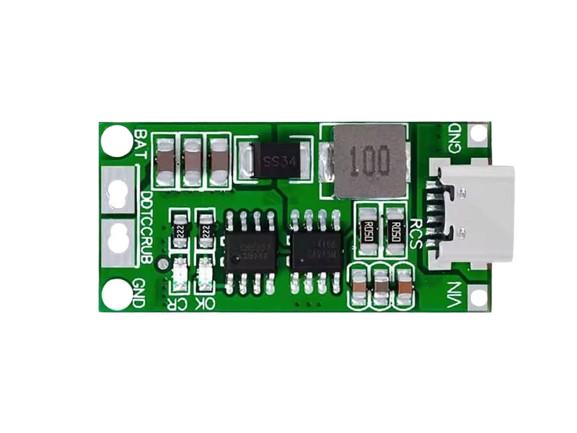
The BMS 2S CHARGER is a Battery Management System designed specifically for 2-cell (2S) lithium battery packs. It plays a critical role in monitoring and managing the charging and discharging processes of lithium-ion or lithium-polymer batteries. By ensuring safety, balancing cell voltages, and protecting against overcharging, over-discharging, and short circuits, the BMS 2S CHARGER helps to prolong battery life and maintain optimal performance.
Explore Projects Built with BMS 2S CHARGER


Explore Projects Built with BMS 2S CHARGER
Common Applications and Use Cases
- Power management for portable electronics
- Lithium battery packs in electric vehicles (EVs)
- Solar energy storage systems
- Uninterruptible Power Supplies (UPS)
- Robotics and drones
- DIY battery-powered projects
Technical Specifications
The following table outlines the key technical details of the BMS 2S CHARGER:
| Parameter | Value |
|---|---|
| Battery Configuration | 2S (2 cells in series) |
| Input Voltage Range | 8.4V (max) |
| Overcharge Protection | 4.25V ± 0.05V per cell |
| Over-discharge Protection | 2.5V ± 0.1V per cell |
| Maximum Charging Current | 3A |
| Maximum Discharging Current | 5A |
| Balance Current | 60mA |
| Operating Temperature Range | -40°C to 85°C |
| Dimensions | 45mm x 17mm x 3mm |
Pin Configuration and Descriptions
The BMS 2S CHARGER typically has the following pin configuration:
| Pin Name | Description |
|---|---|
| B+ | Positive terminal of the battery pack |
| B- | Negative terminal of the battery pack |
| P+ | Positive terminal for load/charger connection |
| P- | Negative terminal for load/charger connection |
| BM | Connection point between the two battery cells |
Usage Instructions
How to Use the BMS 2S CHARGER in a Circuit
Connect the Battery Pack:
- Connect the positive terminal of the battery pack to the
B+pin. - Connect the negative terminal of the battery pack to the
B-pin. - Connect the midpoint between the two cells to the
BMpin.
- Connect the positive terminal of the battery pack to the
Connect the Load and Charger:
- Attach the positive terminal of the load or charger to the
P+pin. - Attach the negative terminal of the load or charger to the
P-pin.
- Attach the positive terminal of the load or charger to the
Verify Connections:
- Double-check all connections to ensure proper polarity and secure contacts.
- Ensure the battery pack is within the supported voltage range (2S configuration).
Power On:
- Once all connections are secure, the BMS will automatically manage the charging and discharging processes.
Important Considerations and Best Practices
- Avoid Overloading: Ensure the load does not exceed the maximum discharging current (5A).
- Use a Compatible Charger: Use a charger designed for 2S lithium battery packs with a maximum output voltage of 8.4V.
- Heat Dissipation: Ensure proper ventilation or heat sinking if the BMS operates under high current conditions.
- Battery Matching: Use cells with similar capacities and internal resistances to ensure proper balancing.
- Do Not Reverse Polarity: Reversing the polarity of the battery or load connections can damage the BMS.
Example: Using the BMS 2S CHARGER with an Arduino UNO
The BMS 2S CHARGER can be used to power an Arduino UNO. Below is an example of how to connect the BMS to the Arduino and monitor the battery voltage:
Circuit Connections
- Connect the
P+andP-pins of the BMS to the Arduino's VIN and GND pins, respectively. - Use a voltage divider circuit to step down the battery voltage for safe monitoring by the Arduino's analog input pin.
Sample Arduino Code
// Define analog pin for voltage monitoring
const int voltagePin = A0;

// Voltage divider resistor values (in ohms)
const float R1 = 10000.0; // Resistor connected to battery positive
const float R2 = 10000.0; // Resistor connected to ground

void setup() {
  Serial.begin(9600); // Initialize serial communication
}

void loop() {
  // Read the analog voltage
  int sensorValue = analogRead(voltagePin);

  // Convert the analog reading to voltage
  float voltage = (sensorValue / 1023.0) * 5.0; // Arduino ADC reference is 5V

  // Calculate the actual battery voltage using the voltage divider formula
  float batteryVoltage = voltage * (R1 + R2) / R2;

  // Print the battery voltage to the Serial Monitor
  Serial.print("Battery Voltage: ");
  Serial.print(batteryVoltage);
  Serial.println(" V");

  delay(1000); // Wait for 1 second before the next reading
}
Troubleshooting and FAQs
Common Issues and Solutions
BMS Not Charging the Battery:
- Cause: Charger voltage is too low or connections are incorrect.
- Solution: Ensure the charger provides 8.4V and check all connections.
Battery Overheating:
- Cause: Excessive charging or discharging current.
- Solution: Reduce the load or use a charger with a lower current rating.
Uneven Cell Voltages:
- Cause: Cells in the battery pack are mismatched.
- Solution: Replace the cells with a matched pair of batteries.
BMS Not Powering the Load:
- Cause: Over-discharge protection has been triggered.
- Solution: Recharge the battery pack to reset the protection circuit.
FAQs
Can I use the BMS 2S CHARGER with a 3S battery pack?
- No, this BMS is specifically designed for 2S (2-cell) configurations. Using it with a 3S pack may result in improper operation or damage.
What happens if I exceed the maximum current rating?
- The BMS will trigger overcurrent protection and disconnect the load to prevent damage.
Do I need to manually balance the cells?
- No, the BMS includes an automatic cell balancing feature to ensure equal voltages across the cells.
Can I use this BMS for LiFePO4 batteries?
- No, this BMS is designed for lithium-ion or lithium-polymer batteries. LiFePO4 batteries have different voltage thresholds and require a dedicated BMS.