Cirkit Designer Logo
Cirkit Designer
Your all-in-one circuit design IDE
Home / 
Component Documentation

How to Use Raspberry Pi 3 A+: Examples, Pinouts, and Specs
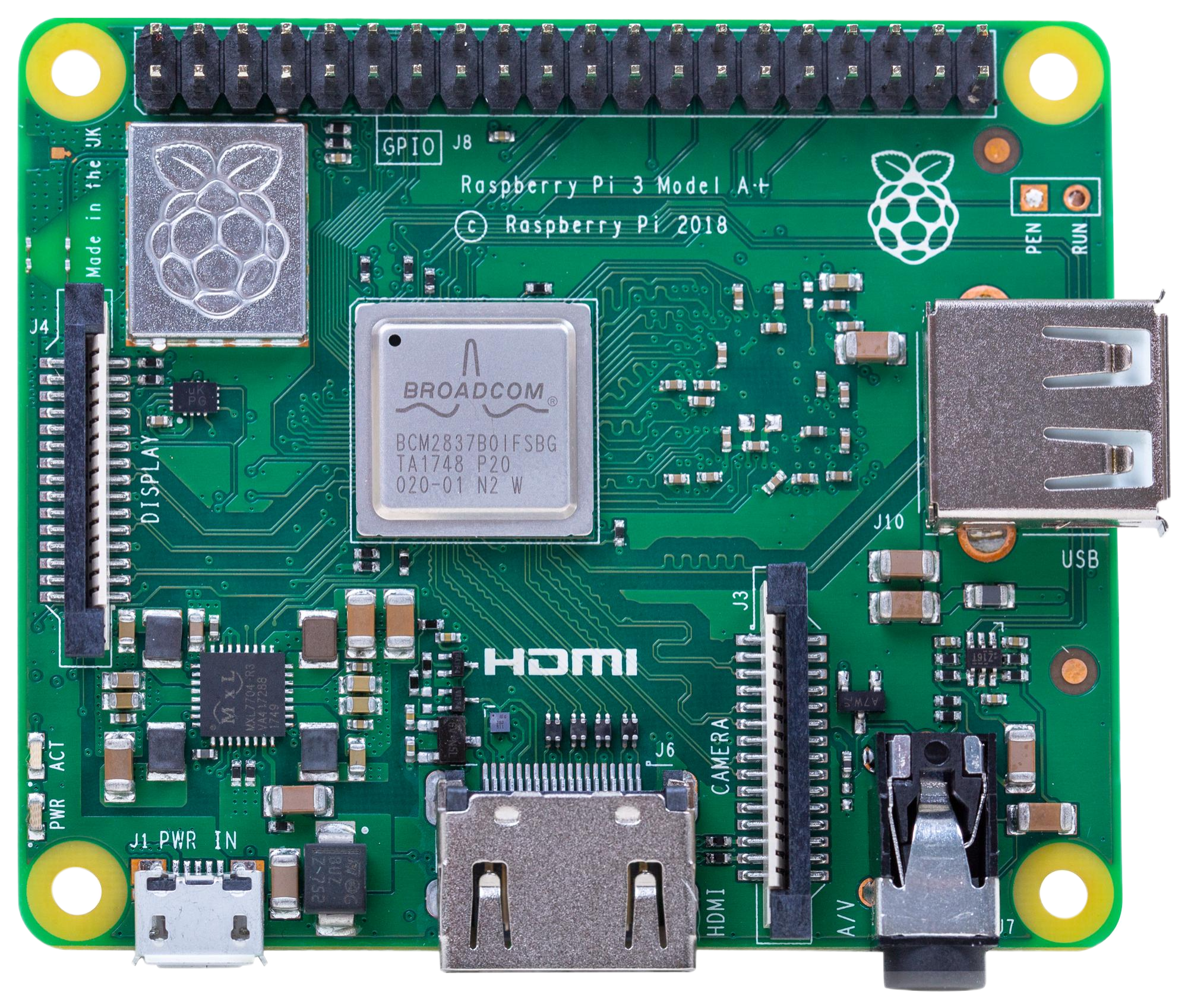

Image of Raspberry Pi 3 A+
Cirkit Designer LogoDesign with Raspberry Pi 3 A+ in Cirkit Designer

Introduction

The Raspberry Pi 3 Model A+ is a compact, low-cost single-board computer developed by Raspberry Pi. It features a quad-core ARM Cortex-A53 processor, 1GB of RAM, and built-in wireless connectivity, including Wi-Fi and Bluetooth. This versatile device is designed for a wide range of applications, from DIY electronics projects to IoT (Internet of Things) systems, robotics, and media centers.

Explore Projects Built with Raspberry Pi 3 A+
Use Cirkit Designer to design, explore, and prototype these projects online. Some projects support real-time simulation. Click "Open Project" to start designing instantly!
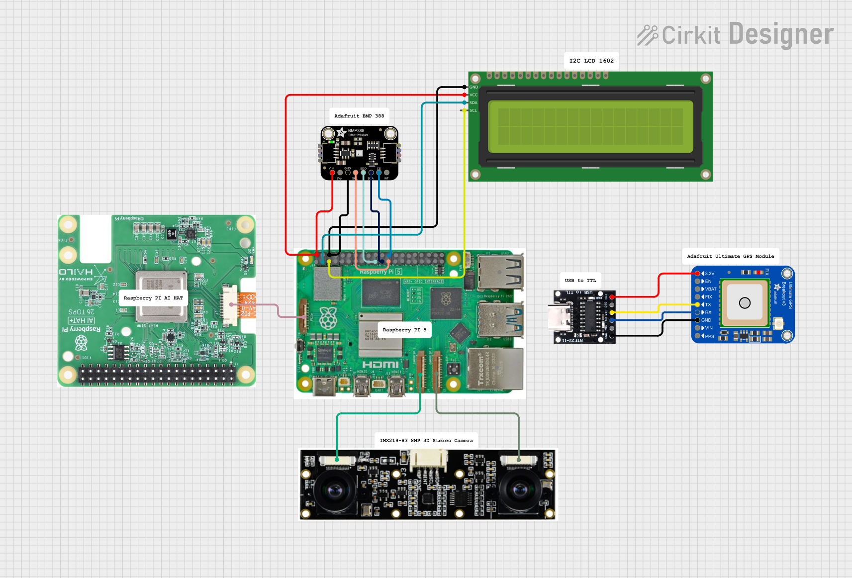
Raspberry Pi 5 Smart Weather Station with GPS and AI Integration
Image of Senior Design: A project utilizing Raspberry Pi 3 A+ in a practical application
This circuit integrates a Raspberry Pi 5 with various peripherals including an 8MP 3D stereo camera, an AI Hat, a BMP388 sensor, a 16x2 I2C LCD, and an Adafruit Ultimate GPS module. The Raspberry Pi serves as the central processing unit, interfacing with the camera for image capture, the AI Hat for AI processing, the BMP388 for environmental sensing, the LCD for display, and the GPS module for location tracking, with a USB Serial TTL for serial communication.
Cirkit Designer LogoOpen Project in Cirkit Designer
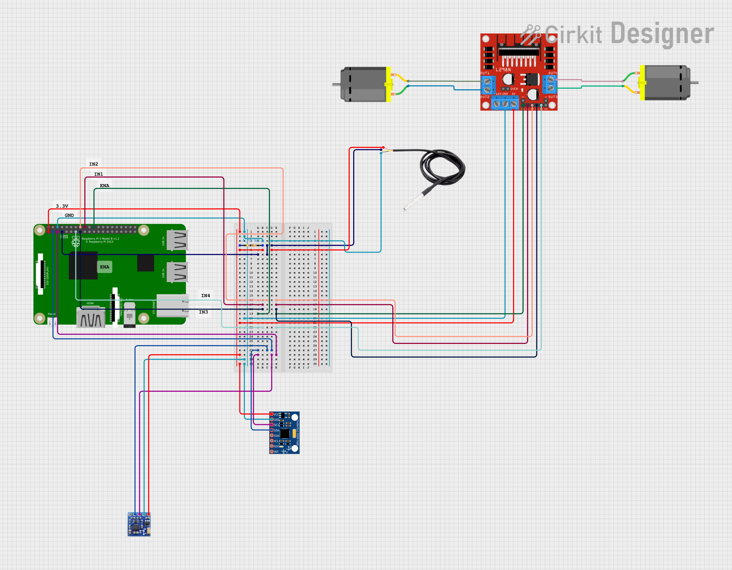
Raspberry Pi 3B-Based Smart Robot with Sensor Integration
Image of Float Robot: A project utilizing Raspberry Pi 3 A+ in a practical application
This circuit integrates a Raspberry Pi 3B with various sensors and a motor driver to create a multi-functional system. It includes a DS18B20 temperature sensor, MPU-6050 accelerometer and gyroscope, QMC5883L magnetometer, and an L298N motor driver controlling two DC motors. The Raspberry Pi handles sensor data and motor control through its GPIO pins.
Cirkit Designer LogoOpen Project in Cirkit Designer
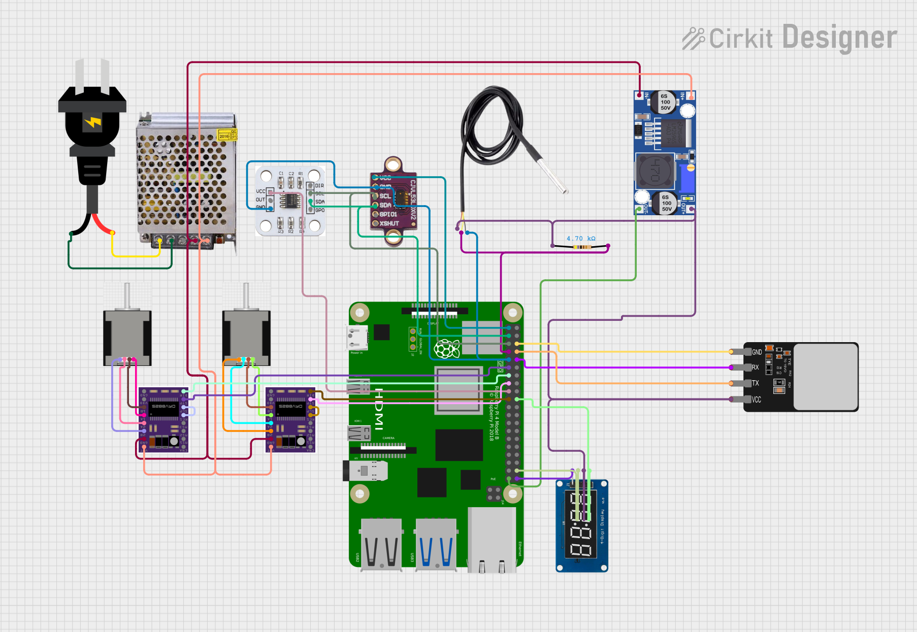
Raspberry Pi 4B-Controlled Biometric Access System with Dual Stepper Motor Actuation
Image of wiring: A project utilizing Raspberry Pi 3 A+ in a practical application
This circuit features a Raspberry Pi 4B as the central controller, interfacing with various sensors and modules. It includes a vl53l0xv2 time-of-flight sensor and an AS5600 magnetic encoder for position sensing, both connected via I2C (SDA/SCL lines). The circuit also controls two DRV8825 stepper motor drivers connected to NEMA 17 stepper motors, receives temperature data from a DS18B20 sensor, and communicates with a fingerprint scanner for biometric input. A TM1637 display module is included for user feedback. Power management is handled by a buck converter and a 12V power supply, with the Raspberry Pi and other 3.3V components powered through the buck converter's regulated output.
Cirkit Designer LogoOpen Project in Cirkit Designer
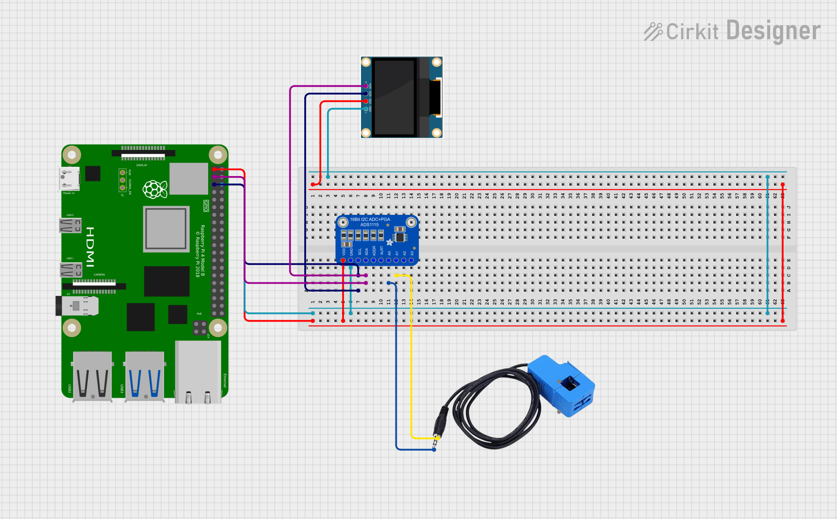
Raspberry Pi 4B with I2C Current Sensing and OLED Display
Image of iot task 2: A project utilizing Raspberry Pi 3 A+ in a practical application
This circuit features a Raspberry Pi 4B as the central processing unit, interfaced with an Adafruit ADS1115 16-bit I2C ADC for analog-to-digital conversion and a 0.96" OLED display for visual output. The ADC is connected to a current sensor for measuring electrical current, with the sensor's output connected to the ADC's AIN0 pin and the burden resistor connected to AIN1. The Raspberry Pi communicates with both the ADC and the OLED display over the I2C bus, using GPIO2 (SDA) and GPIO3 (SCL) for data exchange.
Cirkit Designer LogoOpen Project in Cirkit Designer

Explore Projects Built with Raspberry Pi 3 A+

Use Cirkit Designer to design, explore, and prototype these projects online. Some projects support real-time simulation. Click "Open Project" to start designing instantly!
Image of Senior Design: A project utilizing Raspberry Pi 3 A+ in a practical application
Raspberry Pi 5 Smart Weather Station with GPS and AI Integration
This circuit integrates a Raspberry Pi 5 with various peripherals including an 8MP 3D stereo camera, an AI Hat, a BMP388 sensor, a 16x2 I2C LCD, and an Adafruit Ultimate GPS module. The Raspberry Pi serves as the central processing unit, interfacing with the camera for image capture, the AI Hat for AI processing, the BMP388 for environmental sensing, the LCD for display, and the GPS module for location tracking, with a USB Serial TTL for serial communication.
Cirkit Designer LogoOpen Project in Cirkit Designer
Image of Float Robot: A project utilizing Raspberry Pi 3 A+ in a practical application
Raspberry Pi 3B-Based Smart Robot with Sensor Integration
This circuit integrates a Raspberry Pi 3B with various sensors and a motor driver to create a multi-functional system. It includes a DS18B20 temperature sensor, MPU-6050 accelerometer and gyroscope, QMC5883L magnetometer, and an L298N motor driver controlling two DC motors. The Raspberry Pi handles sensor data and motor control through its GPIO pins.
Cirkit Designer LogoOpen Project in Cirkit Designer
Image of wiring: A project utilizing Raspberry Pi 3 A+ in a practical application
Raspberry Pi 4B-Controlled Biometric Access System with Dual Stepper Motor Actuation
This circuit features a Raspberry Pi 4B as the central controller, interfacing with various sensors and modules. It includes a vl53l0xv2 time-of-flight sensor and an AS5600 magnetic encoder for position sensing, both connected via I2C (SDA/SCL lines). The circuit also controls two DRV8825 stepper motor drivers connected to NEMA 17 stepper motors, receives temperature data from a DS18B20 sensor, and communicates with a fingerprint scanner for biometric input. A TM1637 display module is included for user feedback. Power management is handled by a buck converter and a 12V power supply, with the Raspberry Pi and other 3.3V components powered through the buck converter's regulated output.
Cirkit Designer LogoOpen Project in Cirkit Designer
Image of iot task 2: A project utilizing Raspberry Pi 3 A+ in a practical application
Raspberry Pi 4B with I2C Current Sensing and OLED Display
This circuit features a Raspberry Pi 4B as the central processing unit, interfaced with an Adafruit ADS1115 16-bit I2C ADC for analog-to-digital conversion and a 0.96" OLED display for visual output. The ADC is connected to a current sensor for measuring electrical current, with the sensor's output connected to the ADC's AIN0 pin and the burden resistor connected to AIN1. The Raspberry Pi communicates with both the ADC and the OLED display over the I2C bus, using GPIO2 (SDA) and GPIO3 (SCL) for data exchange.
Cirkit Designer LogoOpen Project in Cirkit Designer

Common Applications and Use Cases

  • IoT Projects: Ideal for smart home automation and sensor-based systems.
  • Media Centers: Can be used with software like Kodi to create a compact media hub.
  • Robotics: Serves as the brain for robots, enabling control and processing.
  • Educational Tools: Perfect for teaching programming and electronics to beginners.
  • DIY Projects: Suitable for custom hardware and software integrations.

Technical Specifications

The Raspberry Pi 3 Model A+ offers a balance of performance and affordability, making it a popular choice for hobbyists and professionals alike.

Key Technical Details

Specification Value
Processor Quad-core ARM Cortex-A53, 1.4GHz
RAM 1GB LPDDR2 SDRAM
Wireless Connectivity 2.4GHz and 5GHz IEEE 802.11b/g/n/ac Wi-Fi
Bluetooth Bluetooth 4.2, BLE
GPIO Pins 40-pin GPIO header
USB Ports 1x USB 2.0
HDMI Output Full-size HDMI
Power Supply 5V/2.5A via micro-USB
Dimensions 65mm x 56mm x 12mm
Weight 29g

Pin Configuration and Descriptions

The Raspberry Pi 3 Model A+ features a 40-pin GPIO header for interfacing with external components. Below is a summary of the pin configuration:

Pin Number Pin Name Description
1 3.3V Power Provides 3.3V power
2 5V Power Provides 5V power
3 GPIO2 (SDA1) I2C Data
4 5V Power Provides 5V power
5 GPIO3 (SCL1) I2C Clock
6 Ground Ground connection
7 GPIO4 General-purpose I/O
8 GPIO14 (TXD0) UART Transmit
9 Ground Ground connection
10 GPIO15 (RXD0) UART Receive
... ... ... (Refer to official documentation)

For the full GPIO pinout, refer to the official Raspberry Pi documentation.

Usage Instructions

How to Use the Raspberry Pi 3 A+ in a Circuit

  1. Powering the Device: Use a 5V/2.5A micro-USB power supply to power the Raspberry Pi 3 A+.
  2. Connecting Peripherals: Attach a keyboard, mouse, and monitor via USB and HDMI ports for initial setup.
  3. Installing an Operating System:
    • Download the Raspberry Pi OS from the official website.
    • Flash the OS image onto a microSD card using tools like Balena Etcher.
    • Insert the microSD card into the Raspberry Pi's card slot.
  4. GPIO Usage:
    • Connect external components (e.g., LEDs, sensors) to the GPIO pins.
    • Use Python libraries like RPi.GPIO or gpiozero to control the pins.

Important Considerations and Best Practices

  • Cooling: Use a heatsink or fan for prolonged high-performance tasks to prevent overheating.
  • Power Supply: Ensure a stable 5V/2.5A power supply to avoid performance issues.
  • Static Protection: Handle the board with care to avoid static discharge damage.
  • Software Updates: Regularly update the OS and software packages for security and performance improvements.

Example: Blinking an LED with GPIO and Python

Below is an example of how to blink an LED connected to GPIO pin 17 using Python:


Import necessary libraries

import RPi.GPIO as GPIO import time

Set up GPIO mode

GPIO.setmode(GPIO.BCM) # Use Broadcom pin numbering GPIO.setup(17, GPIO.OUT) # Set GPIO pin 17 as an output

try: while True: GPIO.output(17, GPIO.HIGH) # Turn LED on time.sleep(1) # Wait for 1 second GPIO.output(17, GPIO.LOW) # Turn LED off time.sleep(1) # Wait for 1 second except KeyboardInterrupt: # Clean up GPIO settings on exit GPIO.cleanup()


Troubleshooting and FAQs

Common Issues and Solutions

  1. Device Does Not Boot:

    • Ensure the microSD card is properly inserted and contains a valid OS image.
    • Verify the power supply provides sufficient voltage and current.
  2. Wi-Fi Connectivity Issues:

    • Check the Wi-Fi credentials and ensure the network is within range.
    • Update the OS to ensure compatibility with the latest Wi-Fi standards.
  3. Overheating:

    • Use a heatsink or fan to improve cooling.
    • Avoid placing the Raspberry Pi in enclosed spaces without ventilation.
  4. GPIO Pins Not Working:

    • Double-check the pin connections and ensure the correct pin numbering is used in the code.
    • Verify that the GPIO pins are not damaged or shorted.

FAQs

  • Q: Can I power the Raspberry Pi 3 A+ via GPIO pins?
    A: Yes, you can power the device using the 5V and GND GPIO pins, but this bypasses the onboard voltage regulation and protection.

  • Q: What is the maximum current output of the GPIO pins?
    A: Each GPIO pin can source/sink up to 16mA, with a total maximum of 50mA across all pins.

  • Q: Can I use the Raspberry Pi 3 A+ for AI/ML applications?
    A: While the Raspberry Pi 3 A+ is not optimized for heavy AI/ML tasks, it can handle lightweight models and edge computing applications.

For additional support, refer to the official Raspberry Pi documentation and forums.