How to Use Security Door Lock System: Examples, Pinouts, and Specs
Introduction
The SYD Security Door Lock System is an advanced electronic locking mechanism designed to enhance the security of residential, commercial, and industrial properties. This system integrates modern access control technologies, such as keypads, RFID readers, and biometric scanners, to prevent unauthorized access. It is a reliable and versatile solution for securing doors, offering both convenience and robust protection.
Explore Projects Built with Security Door Lock System
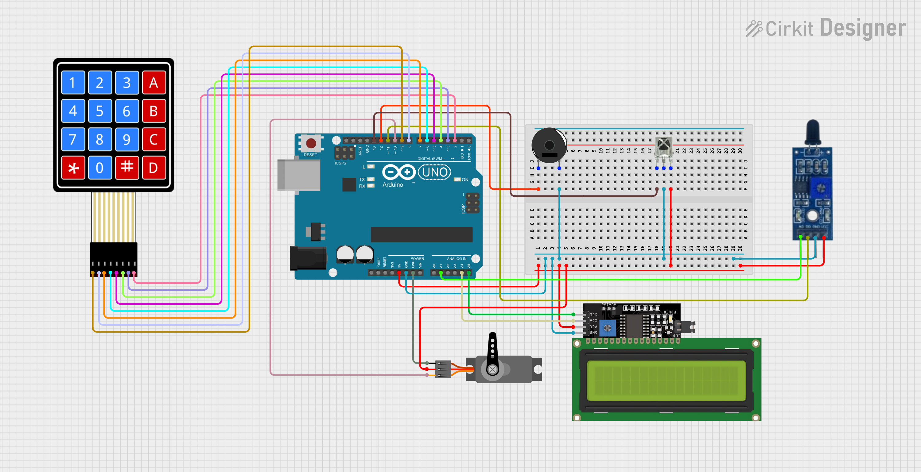
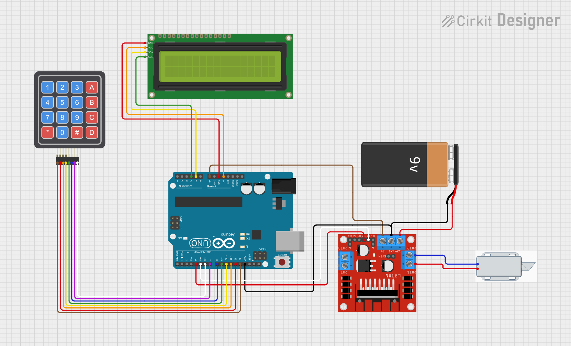
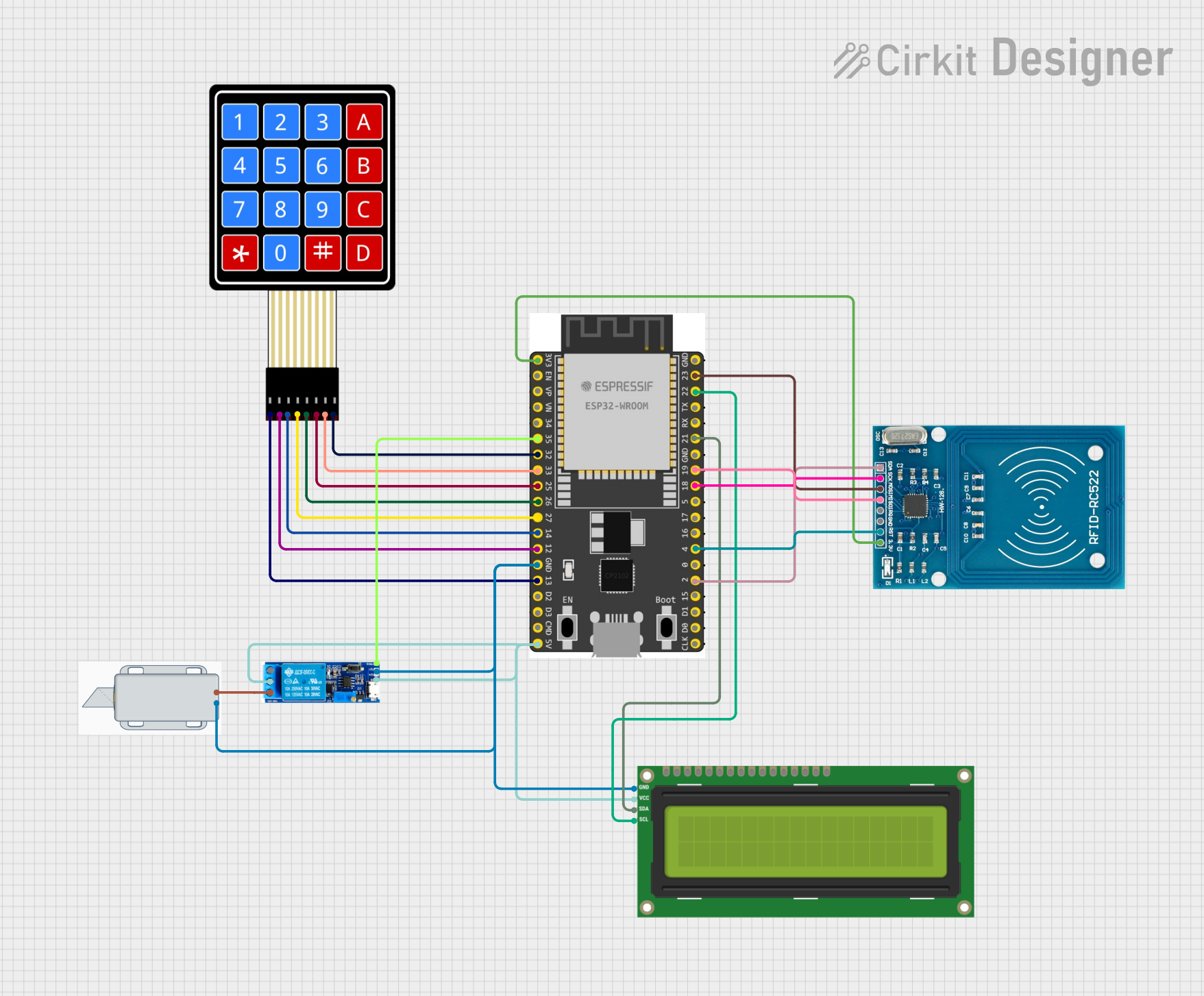
Explore Projects Built with Security Door Lock System
Common Applications and Use Cases
- Residential homes for enhanced safety and convenience.
- Office buildings to control employee access.
- Warehouses and industrial facilities for restricted area security.
- Hotels and rental properties for temporary access control.
- Smart home systems integrated with IoT devices.
Technical Specifications
Key Technical Details
| Parameter | Specification |
|---|---|
| Operating Voltage | 12V DC |
| Current Consumption | 100mA (standby), 500mA (active) |
| Lock Type | Electromagnetic or motorized deadbolt |
| Access Methods | Keypad, RFID, Biometric Scanner |
| Communication Interface | UART, I2C, or GPIO |
| Operating Temperature | -20°C to 60°C |
| Dimensions | 150mm x 80mm x 30mm |
| Weight | 500g |
Pin Configuration and Descriptions
| Pin Number | Pin Name | Description |
|---|---|---|
| 1 | VCC | Power input (12V DC) |
| 2 | GND | Ground connection |
| 3 | DATA_IN | Data input for access control (e.g., keypad) |
| 4 | DATA_OUT | Data output for status or communication |
| 5 | LOCK_CONTROL | Signal to control the locking mechanism |
| 6 | BUZZER | Output for buzzer or alarm |
| 7 | LED_INDICATOR | Output for LED status indicator |
| 8 | RESET | Reset pin to restore factory settings |
Usage Instructions
How to Use the Component in a Circuit
- Power Connection: Connect the VCC pin to a 12V DC power supply and the GND pin to the ground.
- Access Control Input: Attach a keypad, RFID reader, or biometric scanner to the
DATA_INpin. - Lock Control: Use the
LOCK_CONTROLpin to activate or deactivate the locking mechanism. This can be done using a microcontroller or a manual switch. - Status Indicators: Connect an LED to the
LED_INDICATORpin to display the lock status (e.g., locked or unlocked). - Buzzer: Optionally, connect a buzzer to the
BUZZERpin for audible feedback during operation. - Reset: Use the
RESETpin to restore the system to its default settings if needed.
Important Considerations and Best Practices
- Ensure the power supply provides a stable 12V DC output to avoid damage to the system.
- Use proper insulation and shielding for wires to prevent interference or short circuits.
- If integrating with a microcontroller (e.g., Arduino UNO), ensure the communication interface (UART, I2C, or GPIO) is correctly configured.
- Regularly clean the biometric scanner or keypad to maintain optimal performance.
- Test the locking mechanism periodically to ensure reliable operation.
Example Code for Arduino UNO Integration
Below is an example of how to control the SYD Security Door Lock System using an Arduino UNO and a keypad for access control.
#include <Keypad.h>

// Define the keypad layout
const byte ROWS = 4; // Four rows
const byte COLS = 4; // Four columns
char keys[ROWS][COLS] = {
  {'1', '2', '3', 'A'},
  {'4', '5', '6', 'B'},
  {'7', '8', '9', 'C'},
  {'*', '0', '#', 'D'}
};
byte rowPins[ROWS] = {9, 8, 7, 6}; // Connect to the row pins of the keypad
byte colPins[COLS] = {5, 4, 3, 2}; // Connect to the column pins of the keypad

Keypad keypad = Keypad(makeKeymap(keys), rowPins, colPins, ROWS, COLS);

const int lockControlPin = 10; // Pin connected to LOCK_CONTROL
const String correctPassword = "1234"; // Set your desired password
String inputPassword = "";

void setup() {
  pinMode(lockControlPin, OUTPUT);
  digitalWrite(lockControlPin, LOW); // Ensure the lock is initially locked
  Serial.begin(9600);
  Serial.println("Security Door Lock System Initialized");
}

void loop() {
  char key = keypad.getKey();

  if (key) {
    Serial.print("Key Pressed: ");
    Serial.println(key);

    if (key == '#') {
      // Check if the entered password is correct
      if (inputPassword == correctPassword) {
        Serial.println("Access Granted");
        digitalWrite(lockControlPin, HIGH); // Unlock the door
        delay(5000); // Keep the door unlocked for 5 seconds
        digitalWrite(lockControlPin, LOW); // Lock the door again
      } else {
        Serial.println("Access Denied");
      }
      inputPassword = ""; // Reset the input password
    } else if (key == '*') {
      // Clear the input password
      inputPassword = "";
      Serial.println("Password Cleared");
    } else {
      // Append the key to the input password
      inputPassword += key;
    }
  }
}
Notes:
- Replace
1234with your desired password. - Ensure the
lockControlPinis connected to theLOCK_CONTROLpin of the SYD Security Door Lock System. - Use a pull-down resistor on the
LOCK_CONTROLpin to prevent floating signals.
Troubleshooting and FAQs
Common Issues and Solutions
The lock does not respond to input.
- Ensure the power supply is connected and providing 12V DC.
- Check the wiring connections, especially the
DATA_INandLOCK_CONTROLpins. - Verify that the microcontroller or access control device is functioning correctly.
The lock remains in the unlocked state.
- Check if the
LOCK_CONTROLpin is receiving the correct signal. - Ensure there are no short circuits or loose connections.
- Check if the
The keypad or biometric scanner is unresponsive.
- Verify the connection to the
DATA_INpin. - Clean the keypad or scanner to remove dirt or debris.
- Verify the connection to the
The system resets unexpectedly.
- Check for voltage fluctuations in the power supply.
- Ensure the
RESETpin is not accidentally triggered.
FAQs
Can this system be powered by a battery?
- Yes, a 12V DC battery can be used, but ensure it has sufficient capacity to handle the current requirements.
Is the system compatible with smart home platforms?
- Yes, the system can be integrated with smart home platforms using a microcontroller or IoT module.
What happens during a power outage?
- The lock will remain in its last state (locked or unlocked). For enhanced security, consider using a backup power source.
Can I change the access password?
- Yes, the password can be updated in the microcontroller code or through the system's configuration interface, depending on the setup.
By following this documentation, users can effectively install, operate, and troubleshoot the SYD Security Door Lock System for optimal performance and security.