How to Use Raspberry Pi Pico W 2040 - front side: Examples, Pinouts, and Specs
Introduction
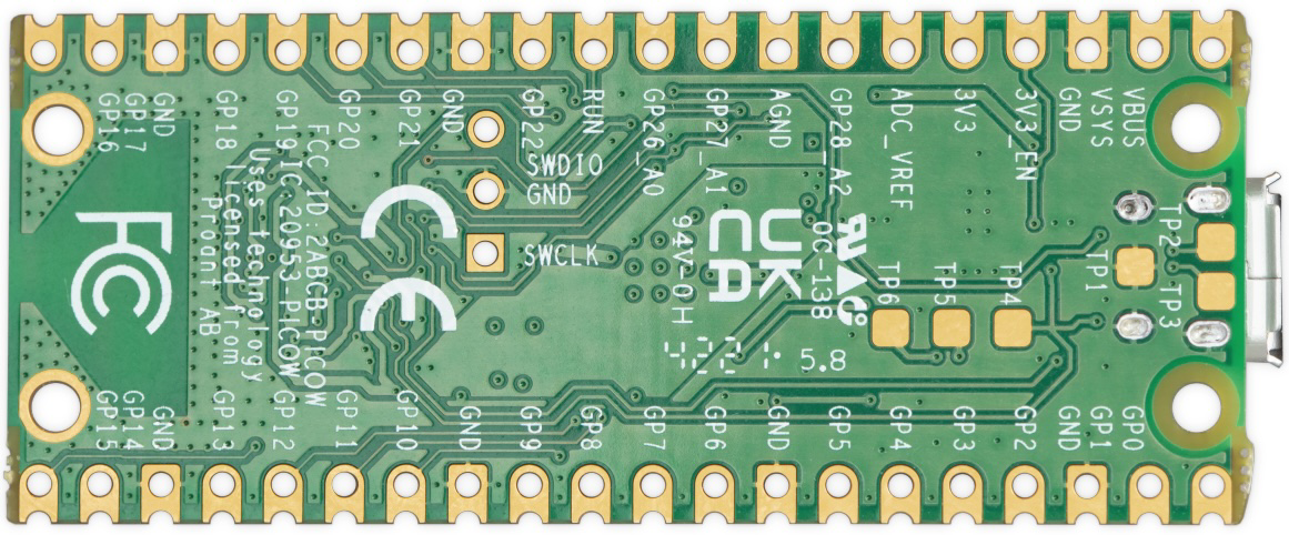
The Raspberry Pi Pico W 2040 is a microcontroller board featuring the RP2040 chip, equipped with Wi-Fi connectivity. It is designed for embedded applications and IoT projects, offering a range of GPIO pins, USB connectivity, and programmable I/O. This versatile board is ideal for hobbyists, educators, and professionals looking to develop innovative projects with ease.
Explore Projects Built with Raspberry Pi Pico W 2040 - front side
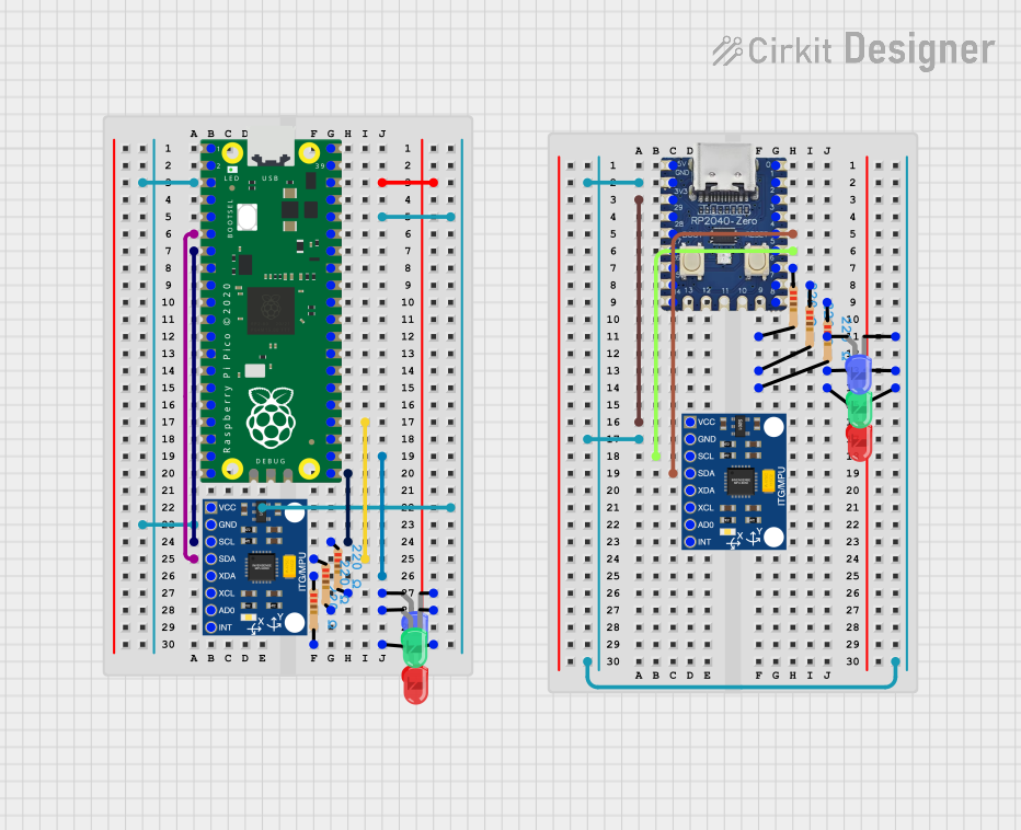
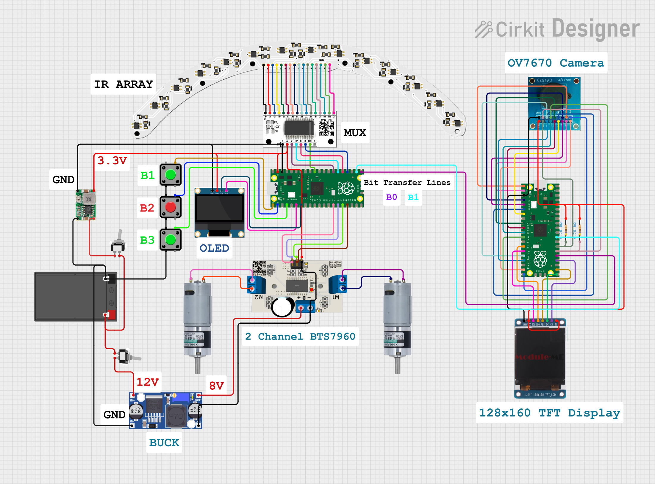
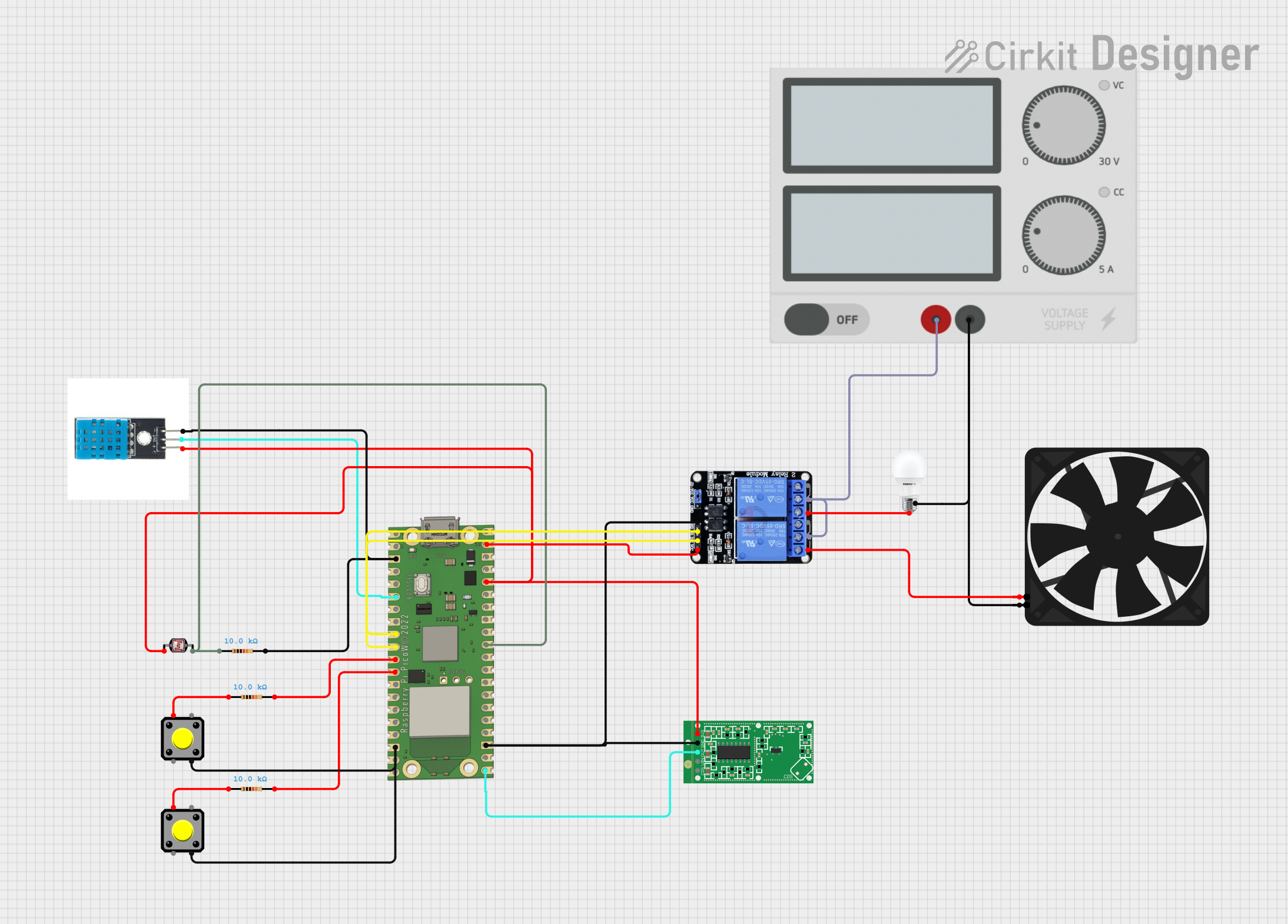
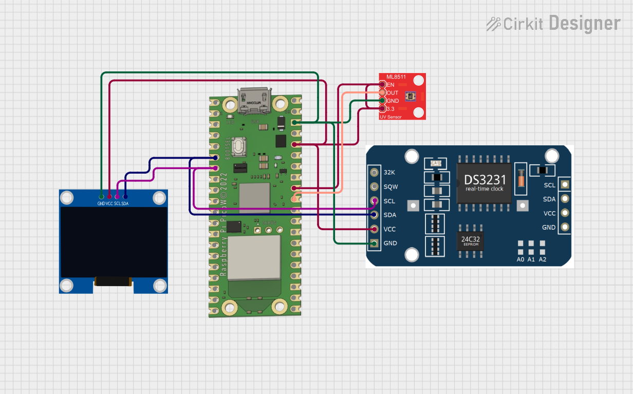
Explore Projects Built with Raspberry Pi Pico W 2040 - front side
Common Applications and Use Cases
- IoT Projects: Connect sensors and actuators to the internet for remote monitoring and control.
- Embedded Systems: Develop custom embedded applications with real-time processing capabilities.
- Educational Projects: Teach and learn programming, electronics, and IoT concepts.
- Prototyping: Quickly prototype and test new ideas and concepts.
Technical Specifications
Key Technical Details
| Specification | Value |
|---|---|
| Microcontroller | RP2040 |
| CPU | Dual-core ARM Cortex-M0+ |
| Clock Speed | 133 MHz |
| Flash Memory | 2 MB |
| SRAM | 264 KB |
| GPIO Pins | 26 |
| Wi-Fi | 802.11n (2.4 GHz) |
| USB | USB 1.1 Host/Device |
| Operating Voltage | 3.3V |
| Input Voltage | 1.8V to 5.5V |
| Power Consumption | 1.8 mA (active mode), 0.2 mA (sleep mode) |
Pin Configuration and Descriptions
| Pin Number | Pin Name | Description |
|---|---|---|
| 1 | GP0 | General Purpose I/O |
| 2 | GP1 | General Purpose I/O |
| 3 | GND | Ground |
| 4 | GP2 | General Purpose I/O |
| 5 | GP3 | General Purpose I/O |
| 6 | GP4 | General Purpose I/O |
| 7 | GP5 | General Purpose I/O |
| 8 | GP6 | General Purpose I/O |
| 9 | GP7 | General Purpose I/O |
| 10 | GP8 | General Purpose I/O |
| 11 | GP9 | General Purpose I/O |
| 12 | GP10 | General Purpose I/O |
| 13 | GP11 | General Purpose I/O |
| 14 | GP12 | General Purpose I/O |
| 15 | GP13 | General Purpose I/O |
| 16 | GP14 | General Purpose I/O |
| 17 | GP15 | General Purpose I/O |
| 18 | GP16 | General Purpose I/O |
| 19 | GP17 | General Purpose I/O |
| 20 | GP18 | General Purpose I/O |
| 21 | GP19 | General Purpose I/O |
| 22 | GP20 | General Purpose I/O |
| 23 | GP21 | General Purpose I/O |
| 24 | GP22 | General Purpose I/O |
| 25 | GP23 | General Purpose I/O |
| 26 | GP24 | General Purpose I/O |
| 27 | GP25 | General Purpose I/O |
| 28 | GP26 | General Purpose I/O |
| 29 | GP27 | General Purpose I/O |
| 30 | GP28 | General Purpose I/O |
| 31 | GND | Ground |
| 32 | 3V3 | 3.3V Power Output |
Usage Instructions
How to Use the Component in a Circuit
Powering the Board:
- Connect the 3.3V pin to a 3.3V power source.
- Connect the GND pin to the ground of your power source.
Connecting to Wi-Fi:
- Use the built-in Wi-Fi module to connect to a wireless network.
- Configure the Wi-Fi settings in your code to establish a connection.
Programming the Board:
- Use the USB port to connect the board to your computer.
- Use the Raspberry Pi Pico SDK or MicroPython to write and upload code.
Using GPIO Pins:
- Connect sensors, actuators, and other peripherals to the GPIO pins.
- Configure the pins as input or output in your code.
Important Considerations and Best Practices
- Voltage Levels: Ensure that the voltage levels of connected devices are compatible with the 3.3V logic level of the Pico W.
- Pin Usage: Avoid using reserved pins for other purposes to prevent conflicts.
- Heat Management: Ensure proper ventilation to prevent overheating during prolonged use.
- Firmware Updates: Keep the firmware updated to benefit from the latest features and bug fixes.
Example Code
Here is an example of how to connect the Raspberry Pi Pico W 2040 to an Arduino UNO and control an LED using MicroPython:
Import necessary libraries
import machine import time
Define the GPIO pin for the LED
led_pin = machine.Pin(25, machine.Pin.OUT)
Blink the LED
while True: led_pin.value(1) # Turn the LED on time.sleep(1) # Wait for 1 second led_pin.value(0) # Turn the LED off time.sleep(1) # Wait for 1 second
Troubleshooting and FAQs
Common Issues Users Might Face
Wi-Fi Connection Issues:
- Solution: Ensure that the Wi-Fi credentials are correct and that the network is within range.
Power Supply Problems:
- Solution: Verify that the power supply provides a stable 3.3V output.
GPIO Pin Malfunction:
- Solution: Check for short circuits or incorrect pin configurations in your code.
USB Connectivity Issues:
- Solution: Ensure that the USB cable is properly connected and that the correct drivers are installed on your computer.
Solutions and Tips for Troubleshooting
- Check Connections: Ensure all connections are secure and correctly oriented.
- Use Debugging Tools: Utilize serial output for debugging and monitoring the board's status.
- Consult Documentation: Refer to the official Raspberry Pi Pico W documentation for detailed information and support.
By following this documentation, users can effectively utilize the Raspberry Pi Pico W 2040 for a wide range of applications, from simple projects to complex IoT systems.