How to Use Relay 2p 5VDC 8A: Examples, Pinouts, and Specs
Introduction
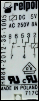
The Relay 2p 5VDC 8A (Manufacturer: Relpol, Part ID: RM84-2012-35-1005) is an electromechanical switch designed to control high-power devices using low-power signals. This relay features two poles (DPDT - Double Pole Double Throw), operates at a 5V DC coil voltage, and can handle loads of up to 8A. It is widely used in applications such as home automation, industrial control systems, and robotics.
Explore Projects Built with Relay 2p 5VDC 8A


Explore Projects Built with Relay 2p 5VDC 8A
Common Applications
- Switching high-power AC or DC loads (e.g., motors, lights, heaters)
- Isolating low-power control circuits from high-power devices
- Home automation systems (e.g., smart switches)
- Industrial equipment and machinery control
- Robotics and IoT projects
Technical Specifications
Key Specifications
| Parameter | Value |
|---|---|
| Manufacturer | Relpol |
| Part ID | RM84-2012-35-1005 |
| Coil Voltage | 5V DC |
| Contact Configuration | DPDT (Double Pole Double Throw) |
| Maximum Switching Current | 8A |
| Maximum Switching Voltage | 250V AC / 30V DC |
| Coil Resistance | 178 Ω |
| Power Consumption | 140 mW |
| Operating Temperature | -40°C to +85°C |
| Dimensions | 29mm x 12.7mm x 15.7mm |
Pin Configuration and Descriptions
The relay has a total of 8 pins. The pinout is as follows:
| Pin Number | Name | Description |
|---|---|---|
| 1 | Coil+ | Positive terminal of the relay coil (5V DC input) |
| 2 | Coil- | Negative terminal of the relay coil (connect to ground) |
| 3 | COM1 | Common terminal for the first pole |
| 4 | NC1 | Normally Closed terminal for the first pole (connected to COM1 when idle) |
| 5 | NO1 | Normally Open terminal for the first pole (connected to COM1 when active) |
| 6 | COM2 | Common terminal for the second pole |
| 7 | NC2 | Normally Closed terminal for the second pole (connected to COM2 when idle) |
| 8 | NO2 | Normally Open terminal for the second pole (connected to COM2 when active) |
Usage Instructions
How to Use the Relay in a Circuit
- Power the Coil: Connect the
Coil+pin to a 5V DC power source and theCoil-pin to ground. This energizes the relay coil and switches the contacts. - Connect the Load:
- For the first pole, connect the load between
COM1and eitherNO1(Normally Open) orNC1(Normally Closed), depending on the desired behavior. - For the second pole, connect the load between
COM2and eitherNO2orNC2.
- For the first pole, connect the load between
- Control the Relay: Use a microcontroller (e.g., Arduino) or a transistor circuit to control the 5V DC signal to the relay coil.
Important Considerations
- Flyback Diode: Always connect a flyback diode (e.g., 1N4007) across the relay coil terminals to protect the driving circuit from voltage spikes when the relay is de-energized.
- Current Ratings: Ensure the load current does not exceed the relay's maximum switching current of 8A.
- Isolation: Use optocouplers or transistors to isolate the control circuit from the relay coil if necessary.
- Power Supply: Use a stable 5V DC power supply to avoid relay malfunction.
Example: Connecting to an Arduino UNO
Below is an example of how to control the relay using an Arduino UNO:
Circuit Connections
- Connect
Coil+to a digital pin on the Arduino (e.g., pin 7) through a transistor (e.g., 2N2222) and a 1kΩ base resistor. - Connect
Coil-to the Arduino's GND. - Add a flyback diode (e.g., 1N4007) across the relay coil terminals.
- Connect the load to the relay's
COMandNOorNCterminals as needed.
Arduino Code
// Relay Control Example
// This code toggles the relay on and off every second.

#define RELAY_PIN 7  // Define the Arduino pin connected to the relay

void setup() {
  pinMode(RELAY_PIN, OUTPUT);  // Set the relay pin as an output
  digitalWrite(RELAY_PIN, LOW); // Ensure the relay is off at startup
}

void loop() {
  digitalWrite(RELAY_PIN, HIGH); // Turn the relay on
  delay(1000);                   // Wait for 1 second
  digitalWrite(RELAY_PIN, LOW);  // Turn the relay off
  delay(1000);                   // Wait for 1 second
}
Troubleshooting and FAQs
Common Issues and Solutions
Relay Not Switching
- Cause: Insufficient voltage or current to the coil.
- Solution: Verify that the coil is receiving 5V DC and sufficient current. Check the power supply and connections.
Load Not Turning On/Off
- Cause: Incorrect wiring of the load to the relay terminals.
- Solution: Double-check the connections to
COM,NO, andNCterminals. Ensure the load is properly connected.
Arduino Pin Not Driving the Relay
- Cause: The Arduino pin cannot supply enough current to drive the relay directly.
- Solution: Use a transistor (e.g., 2N2222) as a switch to control the relay.
Relay Buzzing Noise
- Cause: Unstable power supply or insufficient coil voltage.
- Solution: Ensure a stable 5V DC power supply and check for loose connections.
FAQs
Q: Can this relay switch both AC and DC loads?
A: Yes, the relay can switch both AC (up to 250V) and DC (up to 30V) loads, provided the current does not exceed 8A.
Q: Is the relay safe for inductive loads like motors?
A: Yes, but you should use a snubber circuit or a flyback diode to protect the relay contacts from arcing caused by inductive loads.
Q: Can I use this relay with a 3.3V microcontroller?
A: Yes, but you will need a transistor or relay driver circuit to step up the control signal to 5V for the relay coil.
Q: What is the lifespan of this relay?
A: The relay has a mechanical lifespan of approximately 10 million operations and an electrical lifespan of around 100,000 operations under rated load conditions.