Cirkit Designer Logo
Cirkit Designer
Your all-in-one circuit design IDE
Home / 
Component Documentation

How to Use LED BadgerArray: Examples, Pinouts, and Specs

Image of LED BadgerArray
Cirkit Designer LogoDesign with LED BadgerArray in Cirkit Designer

Introduction

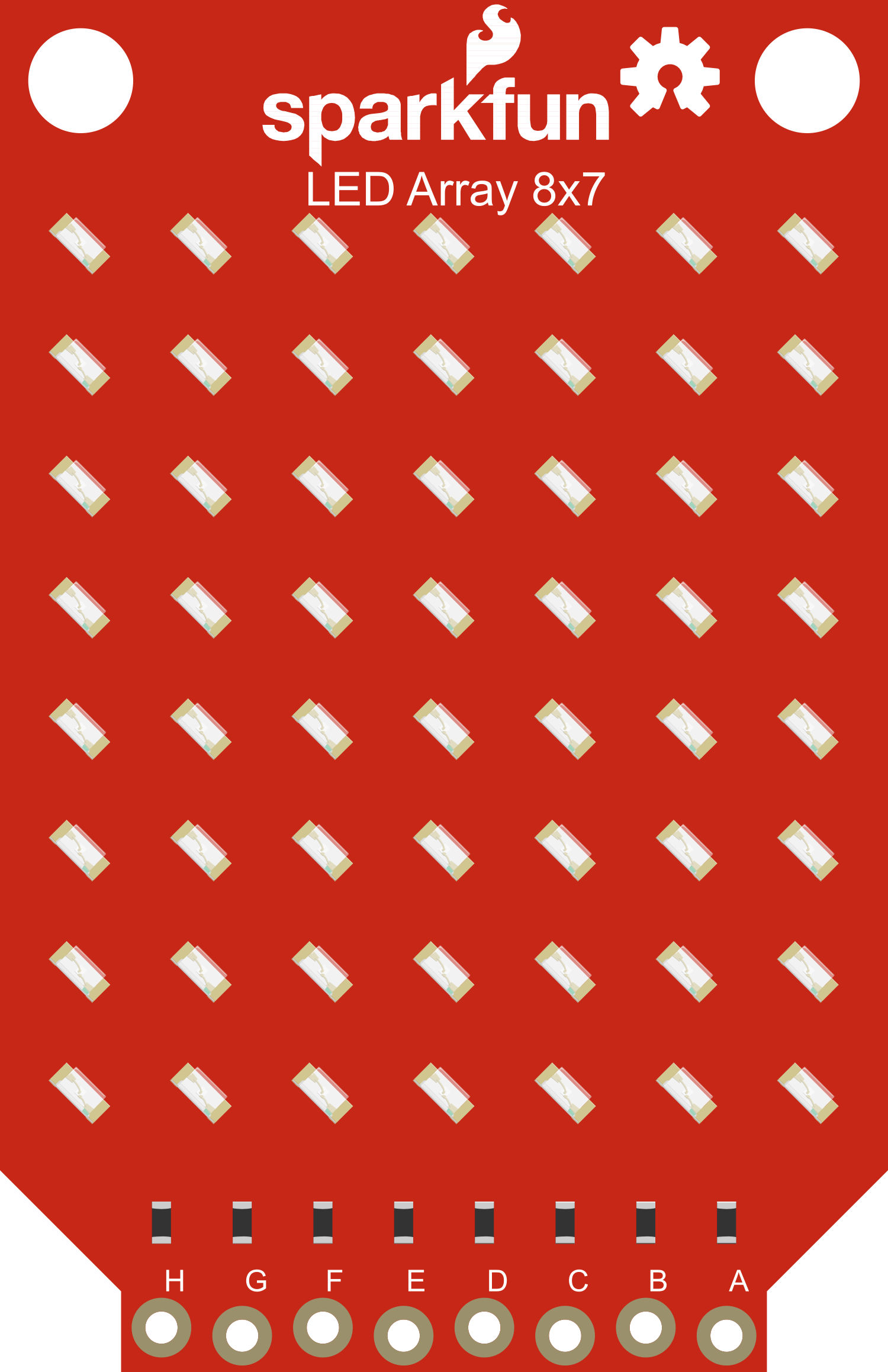
The LED BadgerArray is a cutting-edge display module that consists of a grid of individually addressable RGB LEDs. This component is designed for hobbyists, engineers, and artists who want to add vibrant visual displays to their projects. With its ability to produce a wide spectrum of colors and dynamic effects, the LED BadgerArray is perfect for creating custom indicators, animations, and interactive art installations.

Explore Projects Built with LED BadgerArray

Use Cirkit Designer to design, explore, and prototype these projects online. Some projects support real-time simulation. Click "Open Project" to start designing instantly!
9V Battery-Powered LED Array with Pushbuttons and Toggle Switch Control
Image of 636 commission: A project utilizing LED BadgerArray in a practical application
This circuit is a parallel array of LEDs, each paired with a resistor to limit current, powered by a 9V battery. A toggle switch controls the power to the circuit, and multiple pushbuttons are included, likely for individual or group LED control.
Cirkit Designer LogoOpen Project in Cirkit Designer
Battery-Powered LED Indicator Circuit with Rocker Switch
Image of battari test: A project utilizing LED BadgerArray in a practical application
This circuit is a simple LED array powered by a 9V battery and controlled by a rocker switch. It includes multiple LEDs (red, green, and yellow) connected in series with resistors to limit current, ensuring safe operation of the LEDs when the switch is turned on.
Cirkit Designer LogoOpen Project in Cirkit Designer
ESP32-Controlled Dual 8x8 LED Matrix Display with NTP Time Synchronization
Image of time: A project utilizing LED BadgerArray in a practical application
This circuit features an ESP32 microcontroller connected to two cascaded 8x8 LED matrix displays, powered by a 3.3V battery. The ESP32 drives the displays to show time and other information, with the code indicating functionality for connecting to WiFi, synchronizing time via NTP, and displaying data on the matrices using custom fonts. Additionally, there is a separate 3.3V battery powering a red LED, which appears to function as a simple indicator light.
Cirkit Designer LogoOpen Project in Cirkit Designer
Battery-Powered LED Array with Dual Switch Control
Image of simple traffic light: A project utilizing LED BadgerArray in a practical application
This circuit features a battery-powered array of red and green LEDs, each string controlled by a toggle switch. A rocker switch is used to manage the overall power supply, potentially allowing the user to select between the LED strings or turn them off. The circuit lacks microcontroller functionality, indicating a simple, direct control lighting system.
Cirkit Designer LogoOpen Project in Cirkit Designer

Explore Projects Built with LED BadgerArray

Use Cirkit Designer to design, explore, and prototype these projects online. Some projects support real-time simulation. Click "Open Project" to start designing instantly!
Image of 636 commission: A project utilizing LED BadgerArray in a practical application
9V Battery-Powered LED Array with Pushbuttons and Toggle Switch Control
This circuit is a parallel array of LEDs, each paired with a resistor to limit current, powered by a 9V battery. A toggle switch controls the power to the circuit, and multiple pushbuttons are included, likely for individual or group LED control.
Cirkit Designer LogoOpen Project in Cirkit Designer
Image of battari test: A project utilizing LED BadgerArray in a practical application
Battery-Powered LED Indicator Circuit with Rocker Switch
This circuit is a simple LED array powered by a 9V battery and controlled by a rocker switch. It includes multiple LEDs (red, green, and yellow) connected in series with resistors to limit current, ensuring safe operation of the LEDs when the switch is turned on.
Cirkit Designer LogoOpen Project in Cirkit Designer
Image of time: A project utilizing LED BadgerArray in a practical application
ESP32-Controlled Dual 8x8 LED Matrix Display with NTP Time Synchronization
This circuit features an ESP32 microcontroller connected to two cascaded 8x8 LED matrix displays, powered by a 3.3V battery. The ESP32 drives the displays to show time and other information, with the code indicating functionality for connecting to WiFi, synchronizing time via NTP, and displaying data on the matrices using custom fonts. Additionally, there is a separate 3.3V battery powering a red LED, which appears to function as a simple indicator light.
Cirkit Designer LogoOpen Project in Cirkit Designer
Image of simple traffic light: A project utilizing LED BadgerArray in a practical application
Battery-Powered LED Array with Dual Switch Control
This circuit features a battery-powered array of red and green LEDs, each string controlled by a toggle switch. A rocker switch is used to manage the overall power supply, potentially allowing the user to select between the LED strings or turn them off. The circuit lacks microcontroller functionality, indicating a simple, direct control lighting system.
Cirkit Designer LogoOpen Project in Cirkit Designer

Common Applications and Use Cases

  • Custom lighting displays
  • Interactive art installations
  • Visual notifications for devices
  • Educational tools for learning electronics and programming
  • Prototyping for commercial LED display products

Technical Specifications

Key Technical Details

  • Operating Voltage: 5V DC
  • Maximum Current per LED: 20mA
  • Total Number of LEDs: 64 (8x8 grid)
  • Communication Protocol: SPI (Serial Peripheral Interface)
  • Refresh Rate: 400 Hz
  • Color Depth: 24-bit (8 bits per color channel)

Pin Configuration and Descriptions

Pin Number Name Description
1 VCC Power supply (5V DC)
2 GND Ground connection
3 DIN Data input for SPI
4 CS Chip select for SPI
5 CLK Clock input for SPI

Usage Instructions

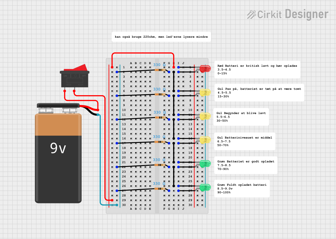
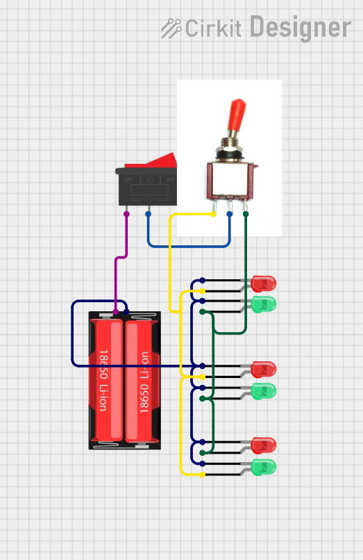
How to Use the Component in a Circuit

  1. Connect the VCC pin to a 5V power supply.
  2. Connect the GND pin to the ground of your power supply.
  3. Connect the DIN, CS, and CLK pins to the corresponding SPI pins on your microcontroller (e.g., Arduino UNO).
  4. Ensure that the power supply can handle the maximum current draw when all LEDs are lit.

Important Considerations and Best Practices

  • Always use a current-limiting resistor or a dedicated LED driver to prevent damage to the LEDs.
  • Avoid powering the LED BadgerArray directly from a microcontroller pin as it may exceed the pin's current rating.
  • Use a separate power supply if the current requirements exceed the capabilities of your microcontroller's voltage regulator.

Example Code for Arduino UNO

#include <SPI.h>

// Define the SPI pins for Arduino UNO
const int csPin = 10; // Chip select pin
const int clkPin = 13; // Clock pin
const int dataPin = 11; // Data input pin

void setup() {
  // Set SPI pins to output
  pinMode(csPin, OUTPUT);
  pinMode(clkPin, OUTPUT);
  pinMode(dataPin, OUTPUT);
  
  // Begin SPI communication
  SPI.begin();
}

void loop() {
  // Select the LED BadgerArray
  digitalWrite(csPin, LOW);
  
  // Send color data for each LED
  for (int i = 0; i < 64; i++) {
    // Replace with the desired color values (R, G, B)
    sendColor(255, 0, 0); // Example: Red color
  }
  
  // Deselect the LED BadgerArray
  digitalWrite(csPin, HIGH);
  
  // A short delay before the next update
  delay(100);
}

void sendColor(byte red, byte green, byte blue) {
  // Send the color data (24 bits: 8 bits for each color channel)
  SPI.transfer(red);
  SPI.transfer(green);
  SPI.transfer(blue);
}

Troubleshooting and FAQs

Common Issues Users Might Face

  • LEDs not lighting up: Check the power supply and connections to ensure proper voltage and ground are provided.
  • Incorrect colors displayed: Verify that the data is being sent in the correct order (RGB) and that the SPI communication is functioning correctly.
  • Flickering or inconsistent lighting: Ensure that the refresh rate is adequate and that there is no excessive voltage drop across the power supply lines.

Solutions and Tips for Troubleshooting

  • Use a multimeter to check for continuity and correct voltage levels.
  • Ensure that the microcontroller's SPI settings match the requirements of the LED BadgerArray.
  • Add capacitors across the power supply lines close to the LED BadgerArray to smooth out voltage fluctuations.

FAQs

Q: Can I chain multiple LED BadgerArrays together? A: Yes, you can chain them by connecting the output pins of one array to the input pins of the next. Make sure to provide adequate power for the increased current draw.

Q: How do I control individual LEDs in the array? A: Individual LEDs are addressed through the SPI protocol. You need to send a sequence of color data corresponding to each LED in the array.

Q: What is the maximum number of LED BadgerArrays I can control with a single microcontroller? A: The maximum number is limited by the microcontroller's memory and the speed of the SPI communication. You will need to test your specific setup to determine this limit.