Cirkit Designer Logo
Cirkit Designer
Your all-in-one circuit design IDE
Home / 
Component Documentation

How to Use ESP32-S3: Examples, Pinouts, and Specs

Image of ESP32-S3
Cirkit Designer LogoDesign with ESP32-S3 in Cirkit Designer

Introduction

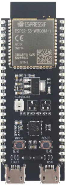
The ESP32-S3-DevKitC-1 v1.1 is a development board created by Espressif Systems featuring the ESP32-S3 SoC, which is a highly integrated and versatile microcontroller designed for a wide range of Internet of Things (IoT) applications. The ESP32-S3 includes Wi-Fi and Bluetooth connectivity, a powerful Xtensa® 32-bit LX7 dual-core processor, and a rich set of peripherals. It is well-suited for smart home devices, industrial automation, wearable electronics, and more.

Explore Projects Built with ESP32-S3

Use Cirkit Designer to design, explore, and prototype these projects online. Some projects support real-time simulation. Click "Open Project" to start designing instantly!
ESP32-S3 Based Automated Watering System with Ultrasonic Sensing and Data Logging
Image of galon otomatis telegram: A project utilizing ESP32-S3 in a practical application
This circuit features an ESP32-S3 microcontroller connected to various peripherals including an HC-SR04 ultrasonic sensor, a water flow sensor, an OLED display, a DS3231 real-time clock (RTC), an SD card module, a water pump, a two-channel relay, and a valve solenoid. The ESP32-S3 manages sensor readings, data logging, and controls the water pump and valve via the relay based on sensor inputs. The circuit is designed for monitoring and controlling water flow, likely in an automated irrigation or fluid management system.
Cirkit Designer LogoOpen Project in Cirkit Designer
ESP32-S3 GPS and Wind Speed Logger with Dual OLED Displays and CAN Bus
Image of esp32-s3-ellipse: A project utilizing ESP32-S3 in a practical application
This circuit features an ESP32-S3 microcontroller interfaced with an SD card module, two OLED displays, a GPS module, and a CAN bus module. The ESP32-S3 records GPS data to the SD card, displays speed on one OLED, and shows wind speed from the CAN bus on the other OLED, providing a comprehensive data logging and display system.
Cirkit Designer LogoOpen Project in Cirkit Designer
ESP32-S3 Based Environmental Monitoring and Control System with Data Logging
Image of ESP32: A project utilizing ESP32-S3 in a practical application
This circuit features an ESP32-S3 microcontroller interfaced with various sensors and modules, including a DHT22 temperature and humidity sensor, an HC-SR04 ultrasonic sensor, an SGP41 VOC and NOx sensor, and an Adafruit INA260 current and power sensor. The ESP32-S3 also controls a DC motor via a relay and communicates with an SD card and an OLED display. An Arduino UNO is used to read inputs from a rotary encoder, and a step-down buck converter is used to regulate voltage from a 12V battery to power the components.
Cirkit Designer LogoOpen Project in Cirkit Designer
ESP32-S3 Based Vibration Detection System with TFT Display and Power Backup
Image of IOT Thesis: A project utilizing ESP32-S3 in a practical application
This circuit features an ESP32-S3 microcontroller connected to various peripherals including an ADXL355 accelerometer, an SW-420 vibration sensor, a buzzer module, and an ILI9341 TFT display. The ESP32-S3 manages sensor inputs and provides output to the display and buzzer. Power management is handled by a 12V to 5V step-down converter, and a UPS ensures uninterrupted power supply, with a rocker switch to control the power flow.
Cirkit Designer LogoOpen Project in Cirkit Designer

Explore Projects Built with ESP32-S3

Use Cirkit Designer to design, explore, and prototype these projects online. Some projects support real-time simulation. Click "Open Project" to start designing instantly!
Image of galon otomatis telegram: A project utilizing ESP32-S3 in a practical application
ESP32-S3 Based Automated Watering System with Ultrasonic Sensing and Data Logging
This circuit features an ESP32-S3 microcontroller connected to various peripherals including an HC-SR04 ultrasonic sensor, a water flow sensor, an OLED display, a DS3231 real-time clock (RTC), an SD card module, a water pump, a two-channel relay, and a valve solenoid. The ESP32-S3 manages sensor readings, data logging, and controls the water pump and valve via the relay based on sensor inputs. The circuit is designed for monitoring and controlling water flow, likely in an automated irrigation or fluid management system.
Cirkit Designer LogoOpen Project in Cirkit Designer
Image of esp32-s3-ellipse: A project utilizing ESP32-S3 in a practical application
ESP32-S3 GPS and Wind Speed Logger with Dual OLED Displays and CAN Bus
This circuit features an ESP32-S3 microcontroller interfaced with an SD card module, two OLED displays, a GPS module, and a CAN bus module. The ESP32-S3 records GPS data to the SD card, displays speed on one OLED, and shows wind speed from the CAN bus on the other OLED, providing a comprehensive data logging and display system.
Cirkit Designer LogoOpen Project in Cirkit Designer
Image of ESP32: A project utilizing ESP32-S3 in a practical application
ESP32-S3 Based Environmental Monitoring and Control System with Data Logging
This circuit features an ESP32-S3 microcontroller interfaced with various sensors and modules, including a DHT22 temperature and humidity sensor, an HC-SR04 ultrasonic sensor, an SGP41 VOC and NOx sensor, and an Adafruit INA260 current and power sensor. The ESP32-S3 also controls a DC motor via a relay and communicates with an SD card and an OLED display. An Arduino UNO is used to read inputs from a rotary encoder, and a step-down buck converter is used to regulate voltage from a 12V battery to power the components.
Cirkit Designer LogoOpen Project in Cirkit Designer
Image of IOT Thesis: A project utilizing ESP32-S3 in a practical application
ESP32-S3 Based Vibration Detection System with TFT Display and Power Backup
This circuit features an ESP32-S3 microcontroller connected to various peripherals including an ADXL355 accelerometer, an SW-420 vibration sensor, a buzzer module, and an ILI9341 TFT display. The ESP32-S3 manages sensor inputs and provides output to the display and buzzer. Power management is handled by a 12V to 5V step-down converter, and a UPS ensures uninterrupted power supply, with a rocker switch to control the power flow.
Cirkit Designer LogoOpen Project in Cirkit Designer

Technical Specifications

Key Technical Details

  • Processor: Xtensa® 32-bit LX7 dual-core
  • Operating Voltage: 3.3V
  • Input Voltage: 5V via USB or Vin pin
  • Digital I/O Pins: 39 (GPIOs)
  • Analog Input Pins: 14 (ADC channels)
  • Analog Output Pins: 2 (DAC channels)
  • Flash Memory: 8 MB
  • SRAM: 512 KB
  • Wi-Fi: 802.11 b/g/n
  • Bluetooth: v5.0 with BLE
  • USB: USB-C for power and programming

Pin Configuration and Descriptions

Pin Number Function Description
1 3V3 3.3V power supply
2 GND Ground
3 EN Reset button; active low
4 IO36 GPIO36, ADC1_CH0, RTC_GPIO0
... ... ...
n IO39 GPIO39, ADC1_CH3, RTC_GPIO3

Note: This is a simplified representation. Please refer to the official datasheet for the complete pinout and functions.

Usage Instructions

Integrating ESP32-S3 into a Circuit

  1. Powering the Board: Ensure that the board is powered through the USB-C connection or via the Vin pin with a regulated 5V supply.
  2. Connecting to Peripherals: Utilize the GPIO pins to connect sensors, actuators, and other components. Be mindful of the voltage levels and current capabilities of each pin.
  3. Programming the Board: Use the USB-C connection to program the board with the ESP-IDF or Arduino IDE. Ensure that the correct drivers are installed on your computer.

Best Practices

  • Always use a current limiting resistor when connecting LEDs to GPIO pins.
  • Use capacitors for power supply decoupling to minimize noise and voltage spikes.
  • Avoid drawing more than 12 mA from any GPIO pin.
  • Ensure proper ESD precautions when handling the board to prevent damage.

Example Code for Arduino UNO

#include <WiFi.h>

// Replace with your network credentials
const char* ssid = "your_SSID";
const char* password = "your_PASSWORD";

void setup() {
  Serial.begin(115200);
  
  // Connect to Wi-Fi
  WiFi.begin(ssid, password);
  while (WiFi.status() != WL_CONNECTED) {
    delay(500);
    Serial.println("Connecting to WiFi...");
  }
  Serial.println("Connected to WiFi");
}

void loop() {
  // Put your main code here, to run repeatedly:
}

Note: This example demonstrates how to connect the ESP32-S3 to a Wi-Fi network. Make sure to replace your_SSID and your_PASSWORD with your actual Wi-Fi credentials.

Troubleshooting and FAQs

Common Issues

  • Board not detected: Ensure that the USB cable is properly connected and the drivers are installed.
  • Wi-Fi not connecting: Verify that the SSID and password are correct and that the Wi-Fi signal is within range.
  • GPIO not functioning: Check if the pin is configured correctly in the code and that there are no shorts or open circuits.

Solutions and Tips

  • Board Reset: If the board is unresponsive, press the EN button to reset it.
  • Firmware Update: Periodically update the firmware and libraries to the latest versions.
  • Power Supply: Use a stable power source to prevent unexpected resets or behavior.

FAQs

Q: Can the ESP32-S3 be used with the Arduino IDE? A: Yes, the ESP32-S3 is compatible with the Arduino IDE. You will need to install the ESP32 board package using the Boards Manager.

Q: What is the maximum current that can be drawn from the 3.3V pin? A: The maximum current draw from the 3.3V pin should not exceed 500 mA.

Q: How can I enable Bluetooth functionality? A: Bluetooth can be enabled using the ESP-IDF or the Arduino IDE with the appropriate libraries and code.

For more detailed information, refer to the Espressif documentation and resources.