How to Use Relay MY2N: Examples, Pinouts, and Specs
Introduction
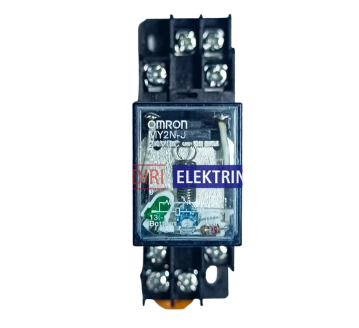
The MY2N relay is an electromagnetic switch designed to control the flow of electricity in a circuit. It operates by using an electromagnet to physically move an armature, thereby opening or closing the electrical contacts within the relay. This allows the relay to control a larger power circuit with a smaller power signal, acting as a form of electrical amplifier. Common applications of the MY2N relay include industrial control systems, home automation, automotive electronics, and various other applications where control of high-power devices by low-power signals is required.
Explore Projects Built with Relay MY2N


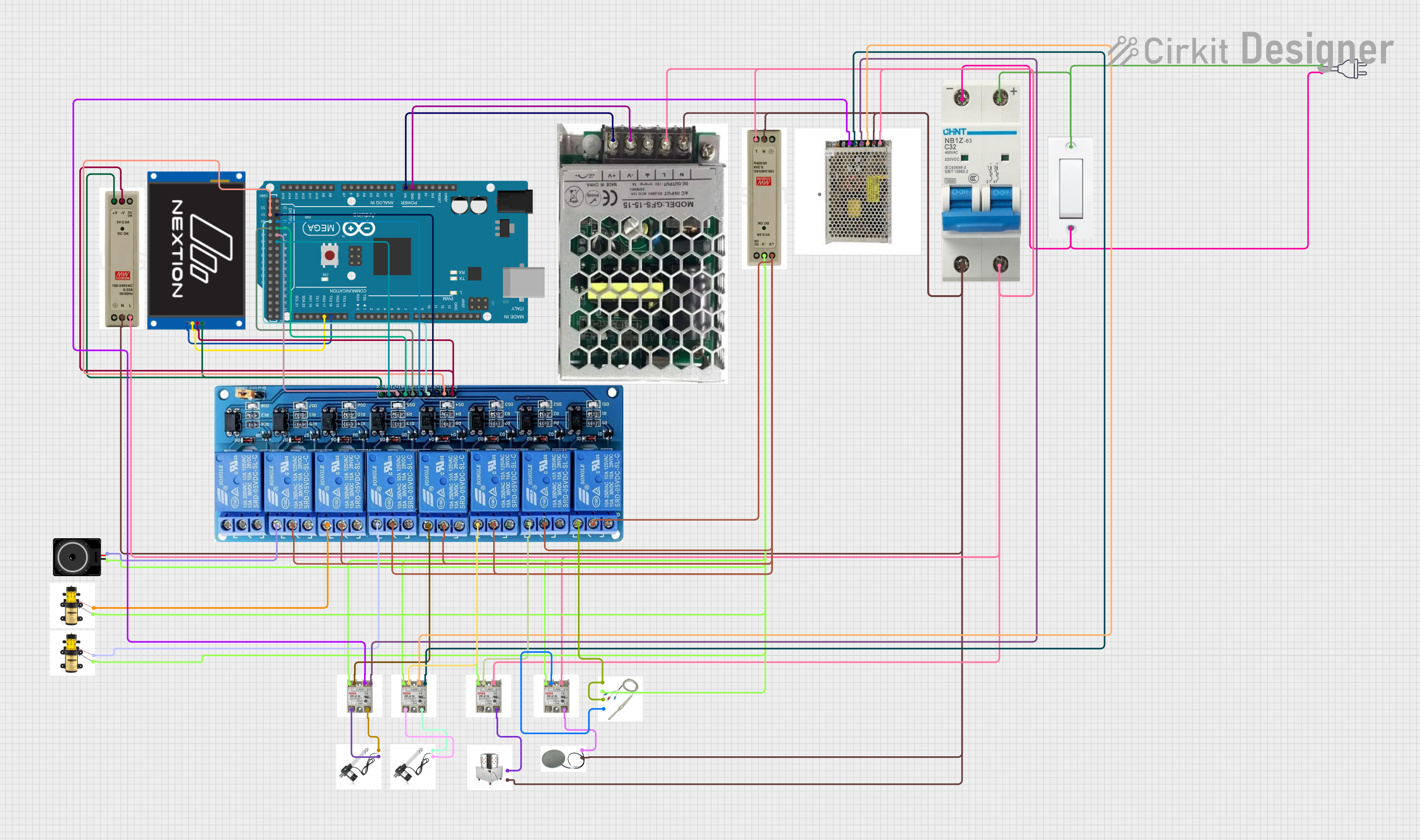

Explore Projects Built with Relay MY2N
Technical Specifications
General Characteristics
- Type: Electromagnetic Relay
- Model: MY2N
- Coil Voltage Options: 12VDC, 24VDC, 110VAC, 220VAC
- Contact Configuration: DPDT (Double Pole Double Throw)
- Contact Rating: 5A at 240VAC / 28VDC
- Operating Time: 15ms max.
- Release Time: 10ms max.
- Electrical Life: 100,000 operations min.
- Mechanical Life: 10,000,000 operations min.
Pin Configuration and Descriptions
| Pin Number | Description |
|---|---|
| 1 | Coil terminal A |
| 2 | Coil terminal B |
| 3 | Common contact for 1st pole |
| 4 | Normally closed for 1st pole |
| 5 | Normally open for 1st pole |
| 6 | Common contact for 2nd pole |
| 7 | Normally closed for 2nd pole |
| 8 | Normally open for 2nd pole |
Usage Instructions
Wiring the Relay
- Connect the coil terminals (pins 1 and 2) to the control circuit that will activate the relay. Ensure that the voltage applied to the coil matches the coil voltage rating of the relay.
- Connect the common contact (pin 3 or 6) to the power source that you want to switch.
- Connect the device you want to control to the normally open (NO) contact (pin 5 or 8) if you want the device to be powered when the relay is activated, or to the normally closed (NC) contact (pin 4 or 7) if you want the device to be powered when the relay is not activated.
Best Practices
- Always check the coil voltage and ensure it matches your control circuit to prevent damage.
- Use a diode across the coil terminals to suppress voltage spikes when the coil is de-energized.
- Ensure that the current and voltage ratings of the contacts are not exceeded by the controlled circuit.
- Consider using a relay socket for easy installation and replacement.
Example Code for Arduino UNO
// Define relay control pin
const int relayPin = 2;

void setup() {
  // Set the relay control pin as an output
  pinMode(relayPin, OUTPUT);
}

void loop() {
  // Turn on the relay (activate the NO contact)
  digitalWrite(relayPin, HIGH);
  delay(1000); // Wait for 1 second

  // Turn off the relay (deactivate the NO contact)
  digitalWrite(relayPin, LOW);
  delay(1000); // Wait for 1 second
}
Troubleshooting and FAQs
Common Issues
- Relay does not activate: Check the control circuit voltage and connections to the coil terminals. Ensure the coil receives the correct voltage.
- Contacts do not switch: Verify that the relay's contacts are not damaged or stuck. Check for proper voltage and current ratings.
- Intermittent operation: Inspect for loose connections or a faulty coil.
FAQs
Q: Can I use the MY2N relay with an AC load? A: Yes, the MY2N relay can switch AC loads up to its rated voltage and current.
Q: How do I know if the relay is activated? A: Some MY2N relay models have an LED indicator. Otherwise, you can use a multimeter to check the continuity across the contacts.
Q: Can I control the MY2N relay with a microcontroller like an Arduino? A: Yes, you can control the relay using a digital output pin from an Arduino or similar microcontroller. Ensure you use a transistor if the coil voltage exceeds the microcontroller's voltage rating.
Q: What is the purpose of the diode across the coil terminals? A: The diode is used to suppress voltage spikes (back EMF) generated when the coil is de-energized, which can damage other components in the circuit.
This documentation provides a comprehensive guide to the MY2N relay, ensuring users can effectively integrate and troubleshoot this component in their electronic projects.