How to Use L298N 2A Dual Motor Driver Module with PWM Control: Examples, Pinouts, and Specs
Introduction
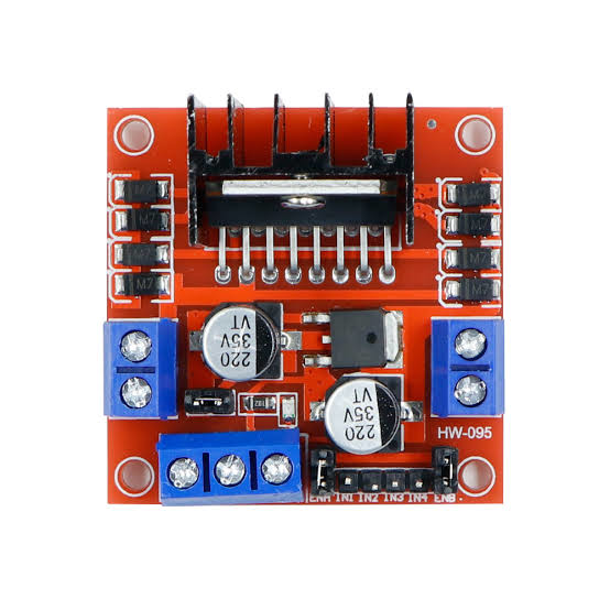
The L298N 2A Dual Motor Driver Module with PWM Control is a versatile and robust module designed to control two DC motors simultaneously with precision and ease. It is widely used in robotics, DIY projects, and educational applications to drive motors that require a significant amount of current and directional control. The module's ability to handle up to 2A per channel makes it suitable for a variety of medium-sized motors.
Explore Projects Built with L298N 2A Dual Motor Driver Module with PWM Control


Explore Projects Built with L298N 2A Dual Motor Driver Module with PWM Control
Common Applications and Use Cases
- Robotics vehicles and platforms
- Automated machinery
- Educational projects and laboratory equipment
- Hobbyist DIY projects involving motor control
Technical Specifications
Key Technical Details
- Operating Voltage (Vcc): 5V to 35V
- Logic Voltage (Vss): 5V (from Arduino board when used)
- Output Current (per channel): Up to 2A
- Peak Output Current (per channel): 3A (non-repetitive)
- PWM Control: Yes, for speed regulation
- Protection: Built-in diodes for back EMF protection
Pin Configuration and Descriptions
| Pin Number | Pin Name | Description |
|---|---|---|
| 1 | OUT1 | Motor A output terminal 1 |
| 2 | OUT2 | Motor A output terminal 2 |
| 3 | OUT3 | Motor B output terminal 1 |
| 4 | OUT4 | Motor B output terminal 2 |
| 5 | Vss | Logic supply voltage (5V) |
| 6 | Vcc | Motor supply voltage (5V-35V) |
| 7 | GND | Ground |
| 8 | ENA | PWM speed control for Motor A |
| 9 | IN1 | Input 1 for Motor A direction control |
| 10 | IN2 | Input 2 for Motor A direction control |
| 11 | IN3 | Input 1 for Motor B direction control |
| 12 | IN4 | Input 2 for Motor B direction control |
| 13 | ENB | PWM speed control for Motor B |
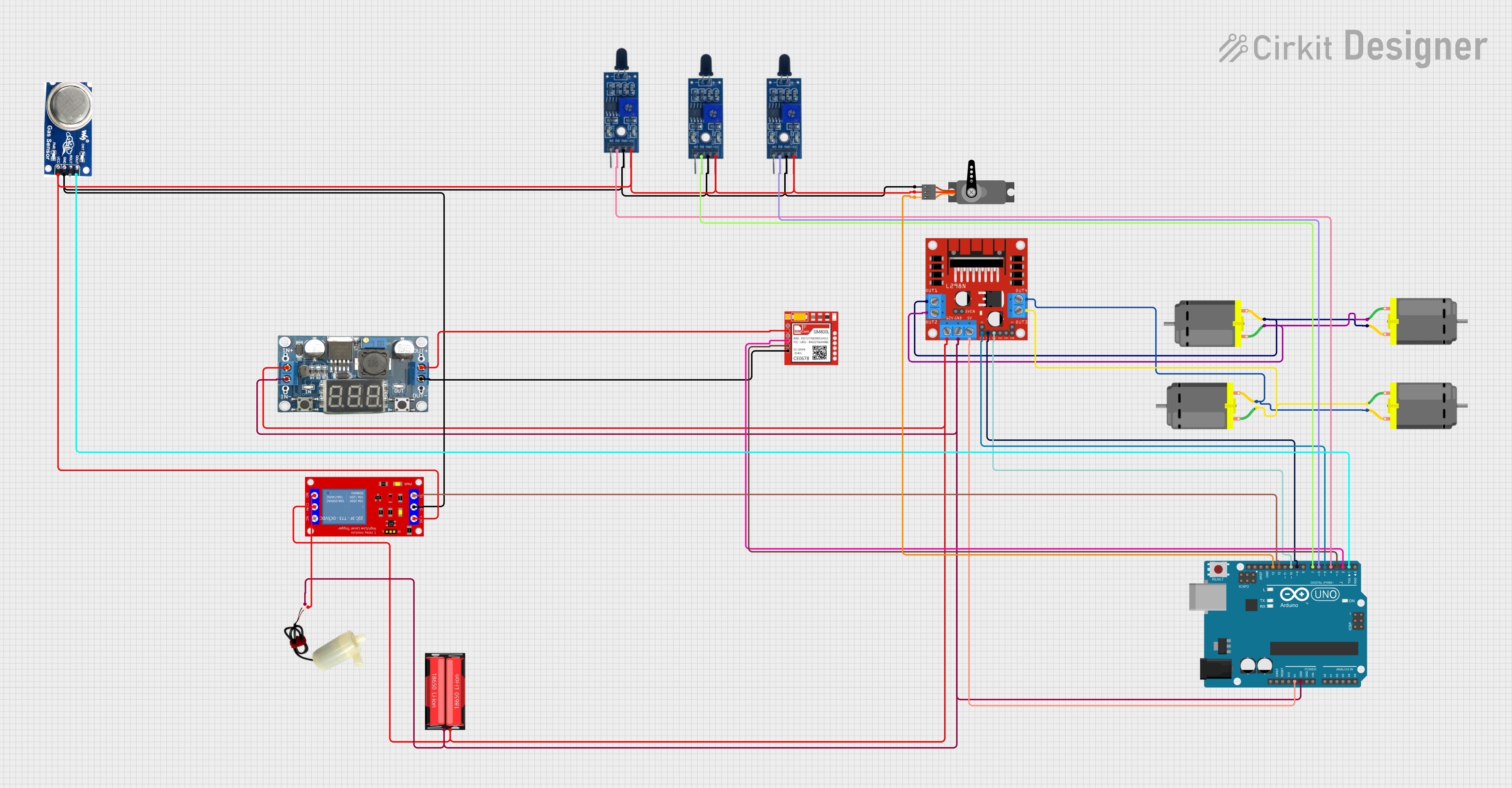
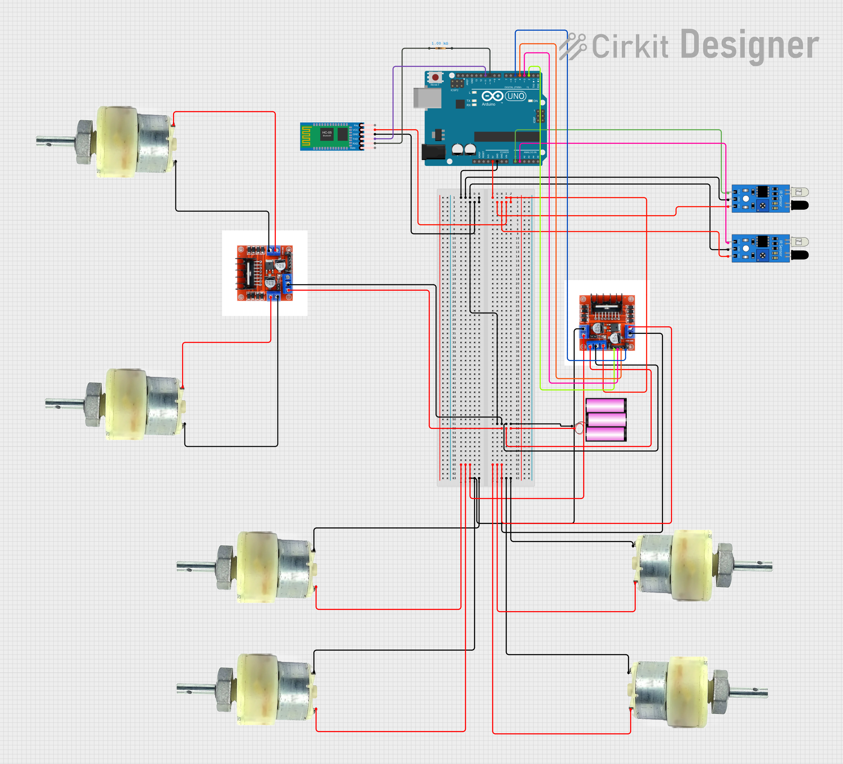
Usage Instructions
How to Use the Component in a Circuit
Power Connections:
- Connect the motor supply voltage (Vcc) to pin 6, ensuring it is within the 5V to 35V range.
- Connect the ground (GND) to pin 7.
- Connect the logic supply voltage (Vss) to pin 5, typically 5V from an Arduino board.
Motor Connections:
- Connect the terminals of Motor A to OUT1 and OUT2.
- Connect the terminals of Motor B to OUT3 and OUT4.
Control Connections:
- Connect IN1 and IN2 to digital outputs on your Arduino for Motor A direction control.
- Connect IN3 and IN4 to digital outputs on your Arduino for Motor B direction control.
- Connect ENA and ENB to PWM-capable digital outputs on your Arduino for speed control.
Important Considerations and Best Practices
- Ensure that the power supply voltage does not exceed the module's maximum rating.
- Use a separate power supply for the motors if the current requirement is high to avoid damaging the Arduino.
- Always use PWM pins on the Arduino for ENA and ENB to enable speed control.
- Incorporate flyback diodes if driving inductive loads to protect against voltage spikes.
Example Arduino Code
// Define motor control pins
#define ENA 9
#define IN1 8
#define IN2 7
#define ENB 10
#define IN3 6
#define IN4 5

void setup() {
  // Set motor control pins as outputs
  pinMode(ENA, OUTPUT);
  pinMode(IN1, OUTPUT);
  pinMode(IN2, OUTPUT);
  pinMode(ENB, OUTPUT);
  pinMode(IN3, OUTPUT);
  pinMode(IN4, OUTPUT);
}

void loop() {
  // Drive Motor A forward at full speed
  digitalWrite(IN1, HIGH);
  digitalWrite(IN2, LOW);
  analogWrite(ENA, 255); // Full speed using PWM signal

  // Drive Motor B backward at half speed
  digitalWrite(IN3, LOW);
  digitalWrite(IN4, HIGH);
  analogWrite(ENB, 127); // Half speed using PWM signal

  delay(2000); // Run motors for 2 seconds

  // Stop both motors
  digitalWrite(IN1, LOW);
  digitalWrite(IN2, LOW);
  digitalWrite(IN3, LOW);
  digitalWrite(IN4, LOW);
  delay(1000); // Wait for 1 second
}
Troubleshooting and FAQs
Common Issues Users Might Face
- Motor not running: Check power supply connections, ensure the logic and motor supply voltages are correct, and verify that the control pins are properly connected to the Arduino.
- Motor running weakly or erratically: Ensure that the power supply can deliver sufficient current for the motors. Check for loose connections and verify that PWM signals are being sent for speed control.
Solutions and Tips for Troubleshooting
- Double-check wiring against the pin configuration table.
- Use a multimeter to verify the presence of voltage at the motor outputs.
- Ensure that the Arduino code is correctly setting the direction and PWM signals.
FAQs
Q: Can I control stepper motors with this module? A: No, the L298N is designed for DC motors. Stepper motors require a different type of driver.
Q: What is the purpose of the ENA and ENB pins? A: ENA and ENB are used for PWM speed control of Motor A and Motor B, respectively.
Q: Can I use a single power supply for both the logic and motor voltages? A: Yes, as long as the power supply meets the voltage and current requirements for both the logic circuit and the motors.
Q: How do I reverse the direction of the motor? A: To reverse the direction, swap the HIGH and LOW states on the IN1/IN2 or IN3/IN4 pairs for the respective motor.
Q: Is it necessary to use PWM for motor control? A: While not strictly necessary, using PWM allows for precise speed control of the motors, which is often desirable in applications requiring variable speeds.