How to Use Grove - I2C Motor Driver (TB6612FNG): Examples, Pinouts, and Specs
Introduction
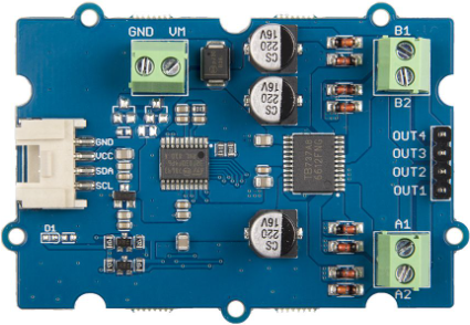
The Grove - I2C Motor Driver (TB6612FNG) is a compact and efficient motor driver module designed by Seeed Studio. It is based on the TB6612FNG motor driver IC, which allows for the control of two DC motors or one stepper motor using I2C communication. This module is ideal for robotics, automation, and other motor control applications where precise and efficient motor operation is required.
Explore Projects Built with Grove - I2C Motor Driver (TB6612FNG)

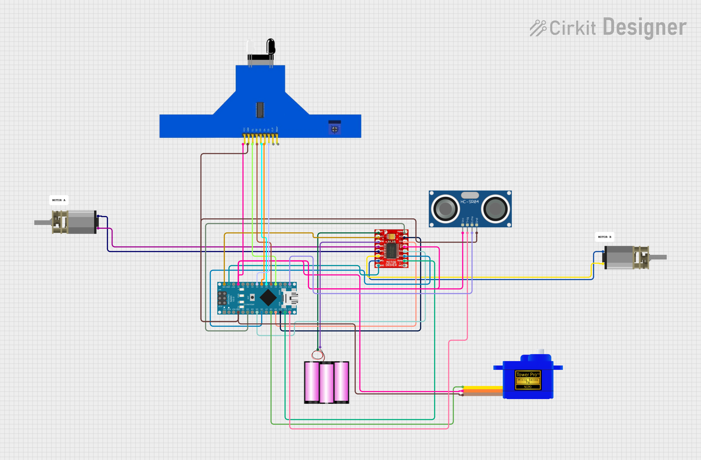
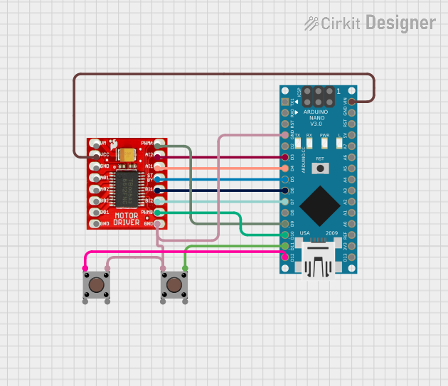
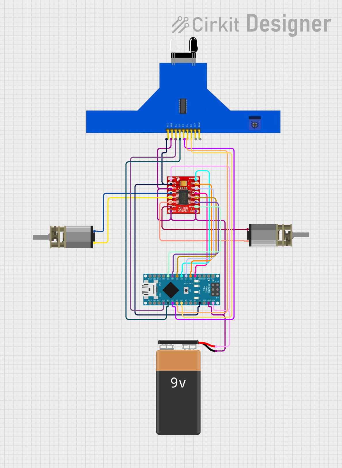
Explore Projects Built with Grove - I2C Motor Driver (TB6612FNG)
Common Applications and Use Cases
- Robotics projects requiring control of multiple DC motors or stepper motors
- Automated conveyor belts and small-scale industrial automation
- DIY motorized vehicles and robotic arms
- Educational projects for learning motor control and I2C communication
Technical Specifications
The following are the key technical details of the Grove - I2C Motor Driver (TB6612FNG):
| Parameter | Specification |
|---|---|
| Manufacturer | Seeed Studio |
| Manufacturer Part ID | 108020103 |
| Motor Driver IC | TB6612FNG |
| Communication Protocol | I2C |
| Operating Voltage | 3.3V to 5V |
| Motor Voltage Range | 4.5V to 13.5V |
| Maximum Output Current | 1.2A per channel (continuous) |
| Peak Output Current | 3.2A per channel (short duration) |
| Number of Channels | 2 (for DC motors) |
| Stepper Motor Support | Yes (1 stepper motor) |
| I2C Address Range | 0x01 to 0x7F (configurable via jumpers) |
| Dimensions | 40mm x 20mm |
Pin Configuration and Descriptions
The Grove - I2C Motor Driver module has the following pin configuration:
| Pin Name | Description |
|---|---|
| VCC | Power supply input (3.3V to 5V) |
| GND | Ground |
| SCL | I2C clock line |
| SDA | I2C data line |
| A1, A2 | Motor A output terminals |
| B1, B2 | Motor B output terminals |
| VM | Motor power supply input (4.5V to 13.5V) |
Usage Instructions
How to Use the Component in a Circuit
Power Connections:
- Connect the
VCCpin to a 3.3V or 5V power source. - Connect the
GNDpin to the ground of your circuit. - Connect the
VMpin to the motor power supply (4.5V to 13.5V) based on your motor's voltage requirements.
- Connect the
I2C Communication:
- Connect the
SCLpin to the I2C clock line of your microcontroller. - Connect the
SDApin to the I2C data line of your microcontroller. - Ensure that the I2C pull-up resistors are present in your circuit (if not already included on the module).
- Connect the
Motor Connections:
- For DC motors, connect the motor terminals to
A1andA2for Motor A, andB1andB2for Motor B. - For a stepper motor, connect the stepper motor's four wires to
A1,A2,B1, andB2.
- For DC motors, connect the motor terminals to
I2C Address Configuration:
- The default I2C address is
0x0F. You can change the address by adjusting the onboard jumpers.
- The default I2C address is
Programming:
- Use an Arduino or other microcontroller to send I2C commands to the module for motor control.
Important Considerations and Best Practices
- Ensure that the motor power supply voltage (
VM) matches the voltage requirements of your motors. - Do not exceed the maximum continuous current rating of 1.2A per channel to avoid damaging the module.
- Use proper heat dissipation methods if operating near the maximum current limits.
- Double-check the I2C address to avoid conflicts with other devices on the same bus.
Example Code for Arduino UNO
Below is an example Arduino sketch to control two DC motors using the Grove - I2C Motor Driver:
#include <Wire.h>

// Default I2C address of the motor driver
#define MOTOR_DRIVER_ADDR 0x0F

// Motor control commands
#define MOTOR_A_FORWARD  0x01
#define MOTOR_A_BACKWARD 0x02
#define MOTOR_B_FORWARD  0x03
#define MOTOR_B_BACKWARD 0x04
#define MOTOR_STOP       0x00

void setup() {
  Wire.begin(); // Initialize I2C communication
  Serial.begin(9600); // Initialize serial communication for debugging
  Serial.println("Grove - I2C Motor Driver Example");
}

void loop() {
  // Send command to move Motor A forward
  sendMotorCommand(MOTOR_A_FORWARD, 100); // Speed: 100 (0-255)
  delay(2000); // Run for 2 seconds

  // Send command to move Motor A backward
  sendMotorCommand(MOTOR_A_BACKWARD, 100);
  delay(2000);

  // Stop Motor A
  sendMotorCommand(MOTOR_STOP, 0);
  delay(1000);

  // Send command to move Motor B forward
  sendMotorCommand(MOTOR_B_FORWARD, 150); // Speed: 150 (0-255)
  delay(2000);

  // Stop Motor B
  sendMotorCommand(MOTOR_STOP, 0);
  delay(1000);
}

// Function to send motor control commands via I2C
void sendMotorCommand(uint8_t command, uint8_t speed) {
  Wire.beginTransmission(MOTOR_DRIVER_ADDR);
  Wire.write(command); // Send motor control command
  Wire.write(speed);   // Send speed value (0-255)
  Wire.endTransmission();
}
Troubleshooting and FAQs
Common Issues and Solutions
Motors Not Running:
- Ensure that the motor power supply (
VM) is connected and within the specified voltage range. - Verify the I2C connections (
SCLandSDA) and ensure proper pull-up resistors are in place. - Check the I2C address and ensure it matches the address in your code.
- Ensure that the motor power supply (
Overheating:
- Avoid exceeding the maximum continuous current rating of 1.2A per channel.
- Use a heat sink or cooling fan if operating near the maximum current limit.
I2C Communication Errors:
- Check for conflicting I2C addresses on the bus.
- Ensure proper wiring and that the I2C lines are not too long, which can cause signal degradation.
Motor Vibrates but Does Not Rotate:
- Verify the motor connections (
A1,A2,B1,B2) and ensure they are correct. - Check the motor power supply voltage and current ratings.
- Verify the motor connections (
FAQs
Q: Can I use this module with a Raspberry Pi?
A: Yes, the module supports I2C communication, which is compatible with Raspberry Pi. Ensure proper voltage level shifting if using a 3.3V Raspberry Pi.
Q: How do I control a stepper motor with this module?
A: Connect the stepper motor's four wires to A1, A2, B1, and B2. Use stepper motor control libraries to send appropriate step sequences via I2C.
Q: What is the default I2C address of the module?
A: The default I2C address is 0x0F. You can change it by adjusting the onboard jumpers.