How to Use 8 Channel IR Sensor: Examples, Pinouts, and Specs
Introduction
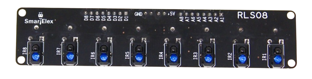
The 8 Channel IR Sensor (HY-S301) is a versatile infrared sensor module capable of detecting infrared signals across eight independent channels. This component is widely used in robotics, automation, and object detection applications. It is particularly useful for line-following robots, obstacle detection, and motion tracking systems. The sensor's ability to monitor multiple channels simultaneously makes it ideal for scenarios requiring precise and multi-directional IR signal detection.
Explore Projects Built with 8 Channel IR Sensor

Explore Projects Built with 8 Channel IR Sensor
Common Applications
- Line-following robots
- Obstacle detection in robotics
- Motion tracking systems
- Industrial automation
- Object counting and sorting systems
Technical Specifications
Below are the key technical details of the HY-S301 8 Channel IR Sensor:
| Parameter | Value |
|---|---|
| Operating Voltage | 3.3V to 5V |
| Operating Current | ≤ 100mA |
| Detection Range | 2cm to 30cm (adjustable) |
| Output Type | Digital (High/Low) |
| Number of Channels | 8 |
| IR Wavelength | 940nm |
| Dimensions | 70mm x 20mm x 10mm |
| Weight | ~10g |
Pin Configuration and Descriptions
The HY-S301 module has a total of 10 pins. Below is the pinout and description:
| Pin | Name | Description |
|---|---|---|
| 1 | VCC | Power supply input (3.3V to 5V). |
| 2 | GND | Ground connection. |
| 3-10 | OUT1-OUT8 | Digital output pins for each of the 8 IR channels. High (1) when IR is detected. |
Usage Instructions
How to Use the Component in a Circuit
- Power the Sensor: Connect the
VCCpin to a 3.3V or 5V power source and theGNDpin to the ground of your circuit. - Connect Outputs: Each of the 8 output pins (
OUT1toOUT8) corresponds to an individual IR sensor. Connect these pins to the input pins of a microcontroller (e.g., Arduino) or other digital logic circuits. - Adjust Sensitivity: Use the onboard potentiometer to adjust the detection range and sensitivity of the IR sensors.
- Read Outputs: Monitor the output pins. A HIGH signal (1) indicates the presence of an object or IR reflection, while a LOW signal (0) indicates no detection.
Important Considerations and Best Practices
- Avoid Ambient IR Interference: Ensure the sensor is not exposed to strong ambient IR sources (e.g., sunlight) to prevent false readings.
- Mounting: Secure the sensor module firmly to avoid misalignment of the IR sensors.
- Power Supply: Use a stable power source to ensure consistent performance.
- Distance Calibration: Adjust the potentiometer to fine-tune the detection range for your specific application.
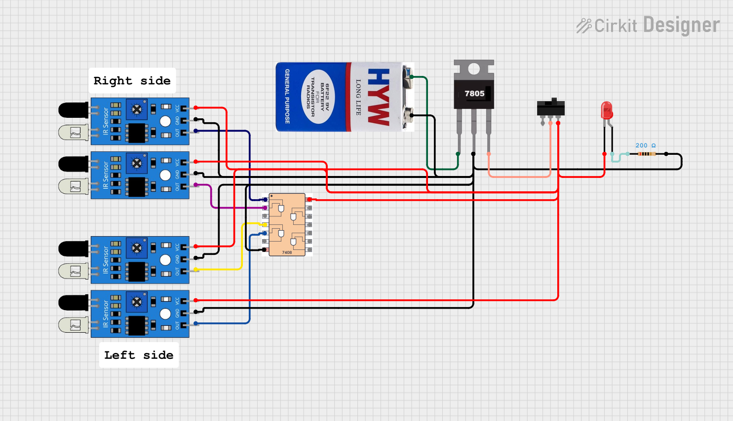
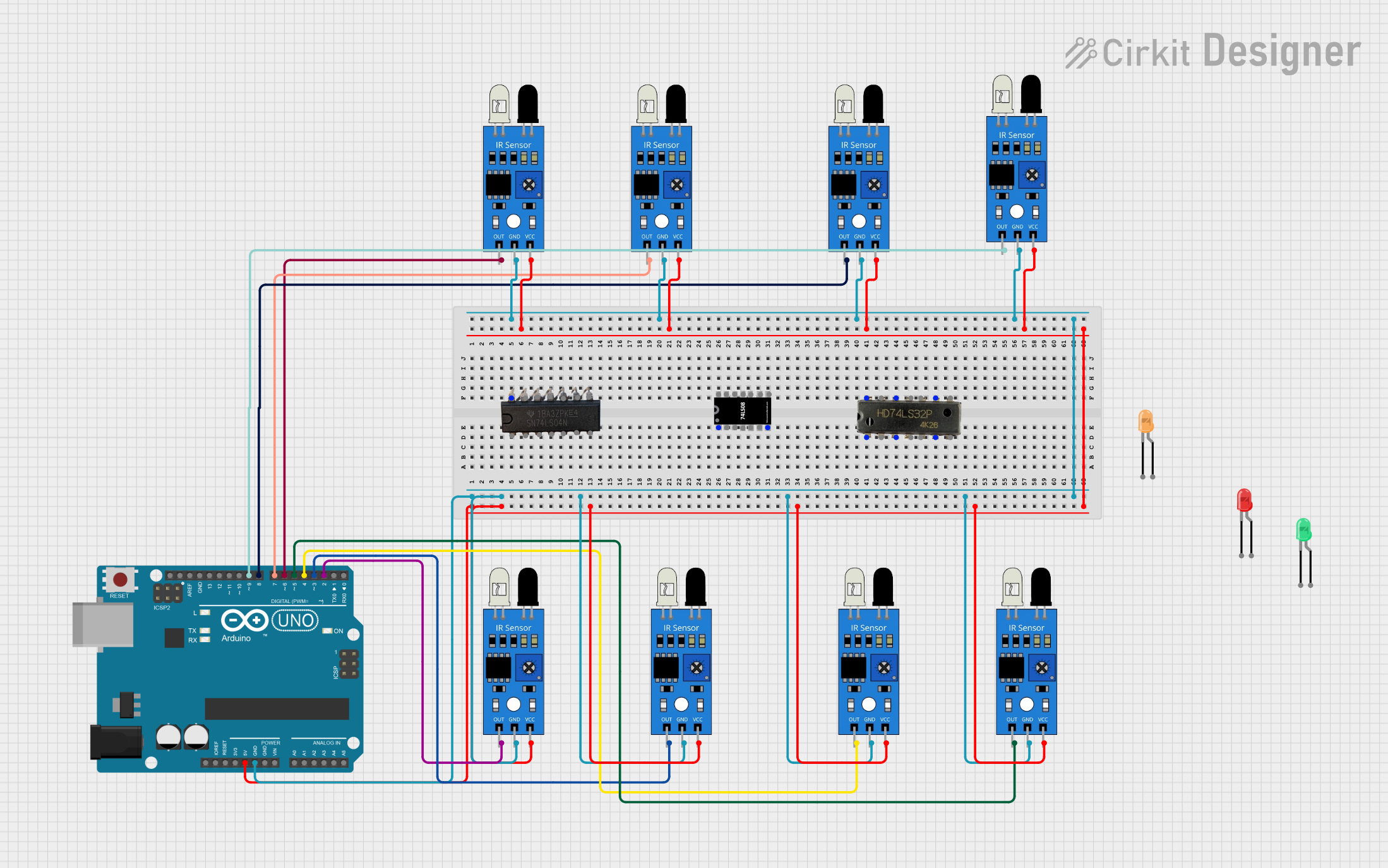
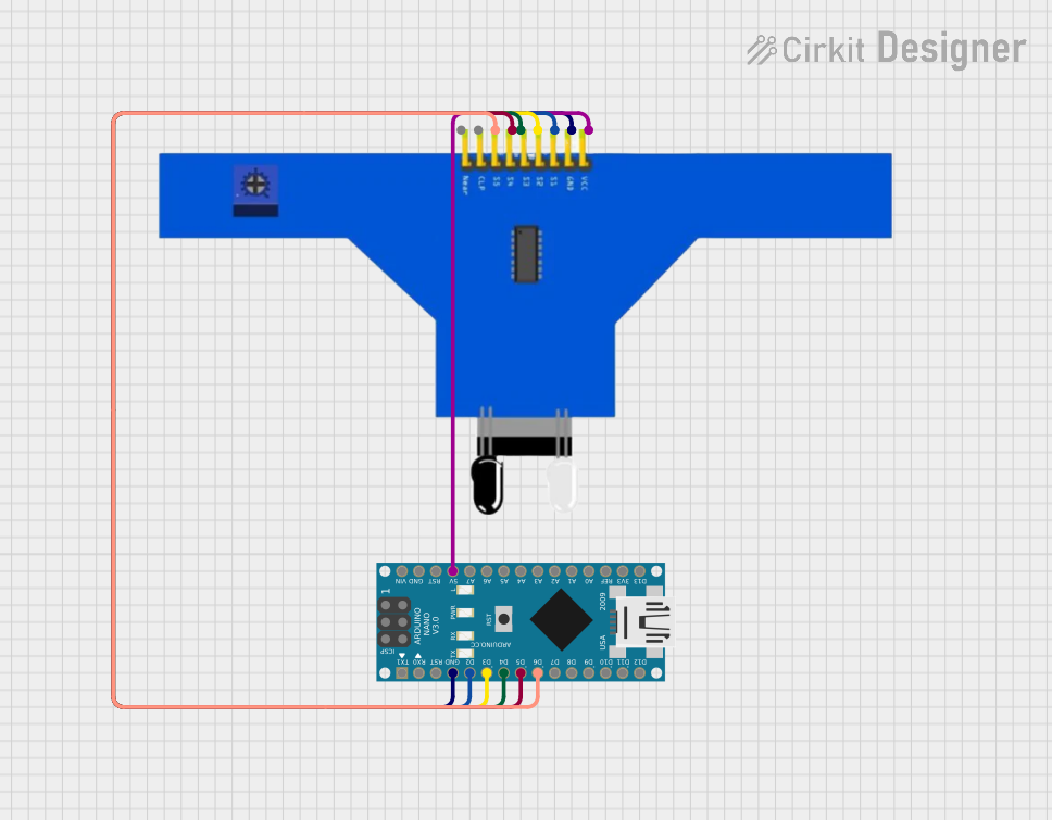
Example: Connecting to an Arduino UNO
Below is an example of how to connect the HY-S301 to an Arduino UNO and read the output from all 8 channels:
Circuit Connections
- Connect
VCCto the Arduino's5Vpin. - Connect
GNDto the Arduino'sGNDpin. - Connect
OUT1toD2,OUT2toD3, ...,OUT8toD9on the Arduino.
Arduino Code
// Define pins for the 8 IR sensor outputs
const int irPins[8] = {2, 3, 4, 5, 6, 7, 8, 9};

void setup() {
  // Initialize serial communication for debugging
  Serial.begin(9600);

  // Set IR sensor pins as inputs
  for (int i = 0; i < 8; i++) {
    pinMode(irPins[i], INPUT);
  }
}

void loop() {
  // Read and print the state of each IR sensor
  Serial.print("IR Sensor States: ");
  for (int i = 0; i < 8; i++) {
    int state = digitalRead(irPins[i]);
    Serial.print(state);
    Serial.print(" "); // Add space between sensor states
  }
  Serial.println(); // Move to the next line
  delay(500); // Wait for 500ms before the next reading
}
Troubleshooting and FAQs
Common Issues and Solutions
No Output Detected:
- Cause: Incorrect wiring or loose connections.
- Solution: Double-check all connections, ensuring
VCCandGNDare properly connected.
False Readings:
- Cause: Ambient IR interference or improper sensitivity settings.
- Solution: Adjust the potentiometer and avoid direct exposure to strong IR sources like sunlight.
Inconsistent Detection Range:
- Cause: Unstable power supply.
- Solution: Use a regulated power source to ensure consistent voltage.
One or More Channels Not Working:
- Cause: Faulty sensor or damaged output pin.
- Solution: Test each channel individually and replace the module if necessary.
FAQs
Q1: Can the sensor detect objects in complete darkness?
A1: Yes, the sensor uses infrared light, which is not dependent on visible light, making it suitable for use in dark environments.
Q2: How do I increase the detection range?
A2: Use the onboard potentiometer to adjust the sensitivity and detection range. Turn it clockwise to increase the range.
Q3: Can I use this sensor with a 3.3V microcontroller?
A3: Yes, the sensor is compatible with both 3.3V and 5V systems.
Q4: What is the maximum detection angle for each channel?
A4: Each IR sensor has a detection angle of approximately 35° to 45°, depending on the environment and object reflectivity.
By following this documentation, you can effectively integrate the HY-S301 8 Channel IR Sensor into your projects and troubleshoot any issues that arise.