
How to Use LED BadgerArray: Examples, Pinouts, and Specs
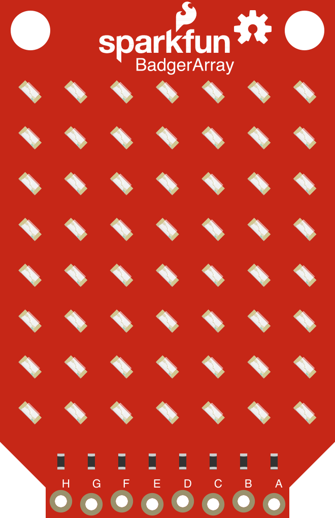
 Design with LED BadgerArray in Cirkit Designer
Introduction
The LED BadgerArray by SparkFun (Manufacturer Part ID: LED BadgerArray) is a compact and versatile array of light-emitting diodes (LEDs) designed for efficient illumination and dynamic visual effects. This component is ideal for applications requiring decorative lighting, status indicators, or programmable displays. Its compact design and ease of integration make it suitable for hobbyists, engineers, and designers alike.
Explore Projects Built with LED BadgerArray
 Open Project in Cirkit Designer
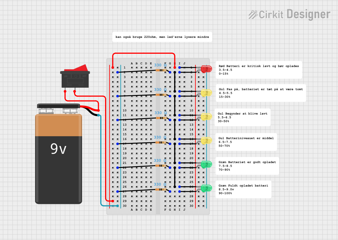 Open Project in Cirkit Designer
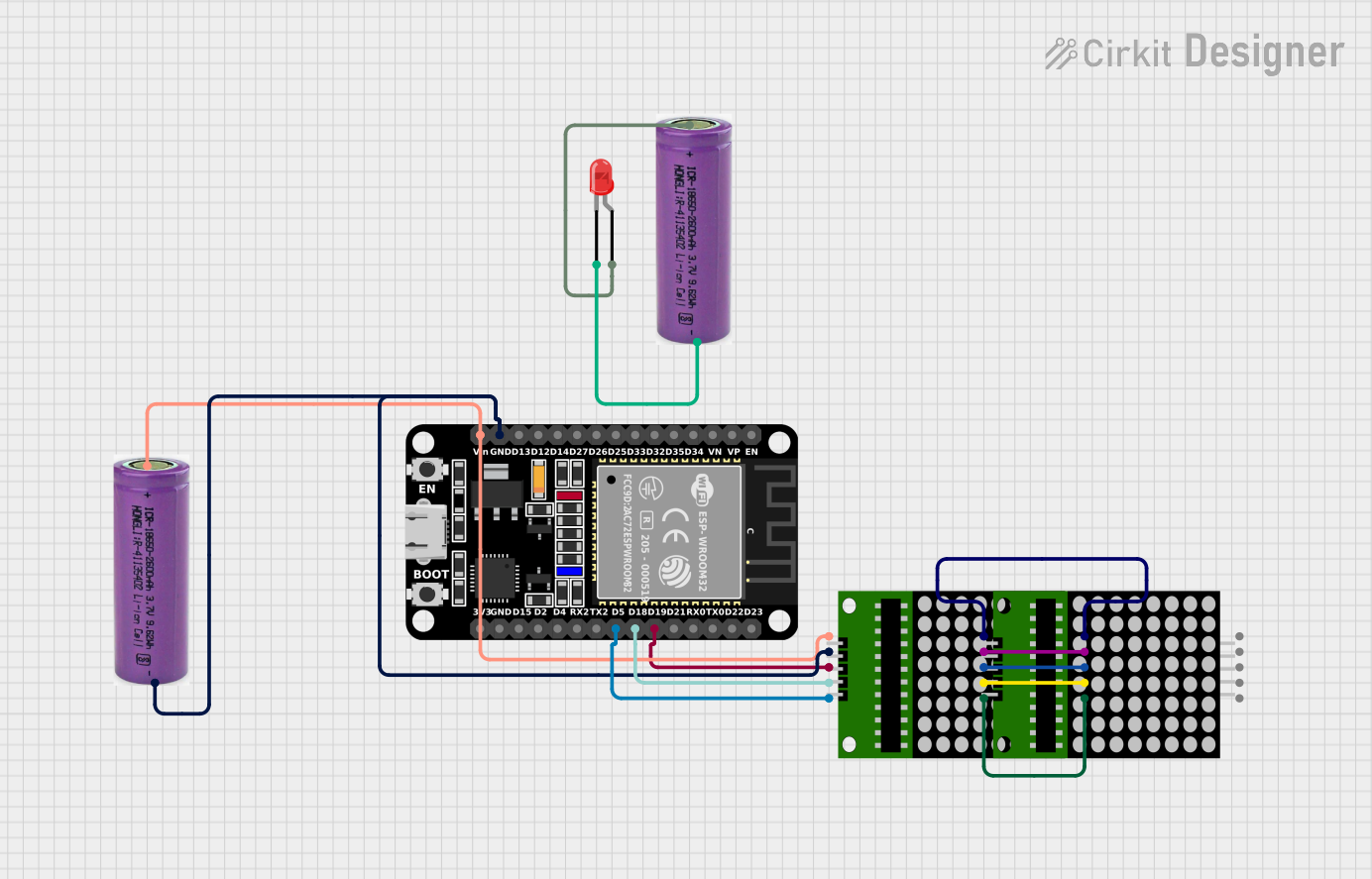 Open Project in Cirkit Designer
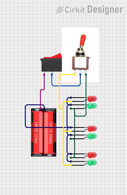 Open Project in Cirkit Designer
Explore Projects Built with LED BadgerArray
Open Project in Cirkit DesignerOpen Project in Cirkit DesignerOpen Project in Cirkit DesignerOpen Project in Cirkit DesignerCommon Applications
- Decorative lighting for homes, events, or installations
- Visual displays and signage
- Status indicators for electronic devices
- Educational projects and prototyping
- Interactive art installations
Technical Specifications
Key Specifications
| Parameter | Value |
|---|---|
| Manufacturer | SparkFun |
| Part ID | LED BadgerArray |
| Operating Voltage | 3.3V to 5V |
| Maximum Current (per LED) | 20mA |
| LED Count | 8 LEDs |
| LED Type | Standard RGB or monochrome |
| Dimensions | 50mm x 10mm x 5mm |
| Mounting Type | Through-hole or solder pads |
| Operating Temperature | -20°C to 70°C |
Pin Configuration
The LED BadgerArray features a simple pinout for easy integration into circuits. Below is the pin configuration:
| Pin Number | Pin Name | Description |
|---|---|---|
| 1 | VCC | Power supply input (3.3V to 5V) |
| 2 | GND | Ground connection |
| 3 | DATA_IN | Data input for controlling the LEDs |
| 4 | DATA_OUT | Data output for chaining multiple arrays |
Usage Instructions
How to Use the LED BadgerArray in a Circuit
- Power Supply: Connect the
VCCpin to a 3.3V or 5V power source and theGNDpin to the ground of your circuit. - Data Input: Use the
DATA_INpin to send control signals to the LED array. This can be done using a microcontroller such as an Arduino. - Chaining Arrays: If you need more LEDs, connect the
DATA_OUTpin of one array to theDATA_INpin of the next array.
Important Considerations
- Current Limiting: Ensure that the current supplied to each LED does not exceed 20mA. Use appropriate resistors or current-limiting circuits if necessary.
- Heat Management: Avoid prolonged operation at maximum brightness to prevent overheating.
- Signal Integrity: Use short and well-shielded wires for the
DATA_INandDATA_OUTconnections to minimize signal degradation.
Example: Connecting to an Arduino UNO
Below is an example of how to control the LED BadgerArray using an Arduino UNO:
// Include the Adafruit NeoPixel library for controlling the LED array
#include <Adafruit_NeoPixel.h>

// Define the pin connected to the DATA_IN pin of the LED BadgerArray
#define LED_PIN 6

// Define the number of LEDs in the array
#define NUM_LEDS 8

// Create a NeoPixel object
Adafruit_NeoPixel strip = Adafruit_NeoPixel(NUM_LEDS, LED_PIN, NEO_GRB + NEO_KHZ800);

void setup() {
  // Initialize the LED strip
  strip.begin();
  strip.show(); // Turn off all LEDs initially
}

void loop() {
  // Example: Cycle through colors on the LED array
  for (int i = 0; i < NUM_LEDS; i++) {
    strip.setPixelColor(i, strip.Color(255, 0, 0)); // Set LED to red
    strip.show(); // Update the LED array
    delay(100); // Wait 100ms
    strip.setPixelColor(i, 0); // Turn off the LED
  }
}
Best Practices
- Use a stable power supply to avoid flickering or inconsistent brightness.
- If chaining multiple arrays, ensure the power supply can handle the total current draw.
- Use appropriate libraries (e.g., Adafruit NeoPixel) for simplified control of the LEDs.
Troubleshooting and FAQs
Common Issues and Solutions
LEDs Not Lighting Up
- Cause: Incorrect wiring or insufficient power supply.
- Solution: Double-check all connections and ensure the power supply meets the voltage and current requirements.
Flickering LEDs
- Cause: Signal degradation or unstable power supply.
- Solution: Use shorter wires for
DATA_INandDATA_OUTconnections. Add a capacitor (e.g., 1000µF) across the power supply to stabilize it.
Incorrect Colors Displayed
- Cause: Incorrect data format or library settings.
- Solution: Verify that the correct LED type (e.g., RGB) and data protocol are selected in your code.
Overheating
- Cause: Prolonged operation at maximum brightness.
- Solution: Reduce brightness levels or add a heat sink if necessary.
FAQs
Q: Can I chain multiple LED BadgerArrays together?
A: Yes, you can chain multiple arrays by connecting the DATA_OUT pin of one array to the DATA_IN pin of the next. Ensure your power supply can handle the total current draw.
Q: What is the maximum number of LEDs I can control with an Arduino?
A: This depends on the memory of your Arduino. For example, an Arduino UNO can typically control up to 500 LEDs using the Adafruit NeoPixel library.
Q: Do I need resistors for the LEDs?
A: The LED BadgerArray is designed to work without external resistors when powered within the specified voltage range. However, adding resistors can provide additional current limiting if needed.
Q: Can I use the LED BadgerArray with a 3.3V microcontroller?
A: Yes, the array is compatible with both 3.3V and 5V logic levels. Ensure the power supply matches the microcontroller's voltage.
By following this documentation, you can effectively integrate the LED BadgerArray into your projects and create stunning visual effects with ease!