How to Use T-Deer Pro Mini LoRa Atmega328P: Examples, Pinouts, and Specs
Introduction
The T-Deer Pro Mini LoRa Atmega328P by LILYGO® is a compact microcontroller board that integrates the power of the ATmega328P processor with LoRa (Long Range) wireless communication capabilities. This board is ideal for Internet of Things (IoT) projects, remote sensor networks, and any application requiring long-range, low-power wireless communication.
Explore Projects Built with T-Deer Pro Mini LoRa Atmega328P

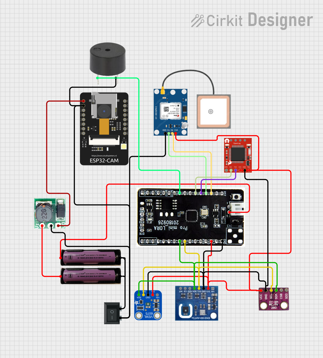

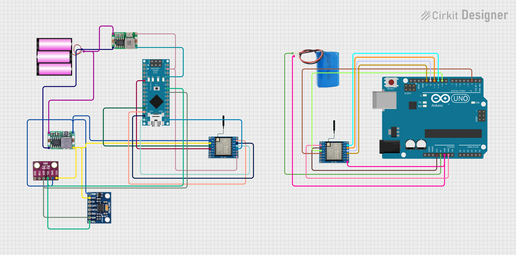
Explore Projects Built with T-Deer Pro Mini LoRa Atmega328P
Common Applications and Use Cases
- Remote environmental monitoring
- Home automation systems
- Agricultural monitoring
- Wildlife tracking
- Smart city infrastructure
Technical Specifications
Key Technical Details
- Microcontroller: ATmega328P
- Operating Voltage: 3.3V
- Input Voltage: 3.35V to 12V
- Digital I/O Pins: 14 (of which 6 provide PWM output)
- Analog Input Pins: 6
- DC Current per I/O Pin: 40 mA
- Flash Memory: 32 KB (ATmega328P) of which 0.5 KB used by bootloader
- SRAM: 2 KB (ATmega328P)
- EEPROM: 1 KB (ATmega328P)
- Clock Speed: 8 MHz
- LoRa Module: SX1276
- Frequency Range: 868 MHz (TTGO T-Deer Pro Mini LoRa V02 868MHz)
- Communication Range: Up to 10 km (subject to environmental conditions)
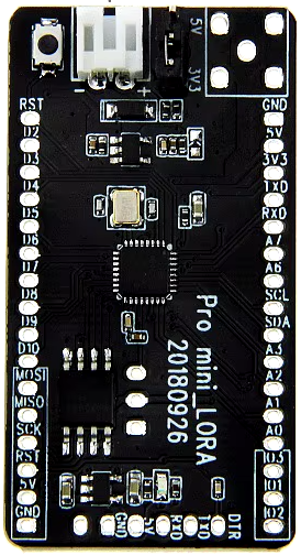
Pin Configuration and Descriptions
| Pin Number | Function | Description |
|---|---|---|
| 1 | Reset | Reset pin, active low |
| 2-13 | Digital I/O | Digital input/output pins |
| 14 | Analog In 0 | Analog input pin 0 |
| 15 | Analog In 1 | Analog input pin 1 |
| ... | ... | ... |
| 19 | Analog In 5 | Analog input pin 5 |
| 20 | AREF | Analog reference voltage for the ADC |
| 21 | GND | Ground |
| 22 | A6 (D4) | Additional analog input (not on DIP package) |
| 23 | A7 (D5) | Additional analog input (not on DIP package) |
| 24 | 3.3V | 3.3V power supply pin |
| 25 | RST | Reset pin for LoRa module |
| 26 | NSS | SPI Chip Select for LoRa module |
| 27 | MOSI | SPI Data Input for LoRa module |
| 28 | MISO | SPI Data Output for LoRa module |
| 29 | SCK | SPI Clock for LoRa module |
| 30 | GND | Ground for LoRa module |
| 31 | 3.3V | 3.3V power supply for LoRa module |
| 32 | DIO0 | Digital I/O for LoRa module (interrupt) |
| 33 | DIO1 | Digital I/O for LoRa module (interrupt) |
Usage Instructions
How to Use the Component in a Circuit
- Powering the Board: Connect a power source within the specified input voltage range to the RAW pin for voltage regulation or directly to the VCC pin if the power supply is already regulated to 3.3V.
- Programming the Board: Use an FTDI programmer or equivalent to upload sketches via the RX and TX pins. Ensure the board is set to 3.3V to match the operating voltage of the T-Deer Pro Mini.
- Connecting LoRa Antenna: Attach an appropriate antenna to the LoRa module's antenna connector to ensure proper communication range and signal integrity.
- Interfacing with Sensors/Actuators: Utilize the digital and analog pins to connect various sensors and actuators, following the pin configuration table.
Important Considerations and Best Practices
- Always ensure that the power supply is within the recommended range to prevent damage to the board.
- When using PWM outputs, ensure that the connected devices can handle the current provided by the pins.
- For LoRa communication, respect local regulations regarding frequency usage and transmission power.
- Use capacitors for power supply decoupling to minimize noise and voltage spikes.
Troubleshooting and FAQs
Common Issues Users Might Face
- Board not responding: Ensure the board is correctly powered and the correct port is selected in the IDE.
- LoRa communication failure: Check the antenna connections and ensure that the frequency settings match the regional standards.
Solutions and Tips for Troubleshooting
- If the board does not appear in the IDE, check the USB to serial adapter connections and drivers.
- For LoRa issues, verify that the SPI connections are secure and that the LoRa library is correctly configured for the frequency band.
FAQs
Q: Can I use the T-Deer Pro Mini LoRa with the Arduino IDE?
- A: Yes, the board is compatible with the Arduino IDE. Select the "Arduino Pro or Pro Mini" board with the processor "ATmega328P (3.3V, 8 MHz)".
Q: What is the maximum range I can achieve with the LoRa module?
- A: The range can be up to 10 km, but this is highly dependent on the environment and antenna used.
Q: How can I save power for battery-operated projects?
- A: Utilize the sleep modes of the ATmega328P and the LoRa module, and minimize the transmission power and frequency.
Example Code for Arduino UNO
#include <SPI.h>
#include <LoRa.h>

// Define the pins used by the LoRa module
#define SS 10
#define RST 9
#define DI0 2

void setup() {
  Serial.begin(9600);
  while (!Serial);

  Serial.println("LoRa Sender");

  // Initialize LoRa module
  LoRa.setPins(SS, RST, DI0);

  if (!LoRa.begin(868E6)) { // Set frequency to 868 MHz
    Serial.println("Starting LoRa failed!");
    while (1);
  }
}

void loop() {
  Serial.print("Sending packet: ");
  Serial.println(counter);

  // Send a message to indicate which packet number is being sent
  LoRa.beginPacket();
  LoRa.print("hello ");
  LoRa.print(counter);
  LoRa.endPacket();

  counter++;

  delay(5000); // Wait for 5 seconds before sending the next packet
}
This example code is for a simple LoRa sender. Ensure that the pin definitions match the connections on your T-Deer Pro Mini LoRa board. Adjust the frequency according to your regional standards and the board's specifications.