How to Use voltage dc module splitter: Examples, Pinouts, and Specs
Introduction
A voltage DC module splitter is a device designed to distribute a single DC voltage input into multiple outputs. This allows for the efficient and organized distribution of power to various components in a circuit while maintaining the same voltage level across all outputs. It is commonly used in projects where multiple devices or modules require the same voltage supply, such as in robotics, IoT systems, and prototyping setups.
Explore Projects Built with voltage dc module splitter


Explore Projects Built with voltage dc module splitter
Common Applications and Use Cases
- Powering multiple sensors or modules in IoT projects.
- Distributing power to multiple LEDs or small motors in robotics.
- Simplifying power management in prototyping and breadboard setups.
- Providing consistent voltage to multiple devices in automotive or industrial systems.
Technical Specifications
Below are the key technical details of a typical voltage DC module splitter:
| Parameter | Specification |
|---|---|
| Input Voltage Range | 5V to 24V DC |
| Output Voltage | Same as input voltage (pass-through) |
| Maximum Output Current | 2A per output (varies by model) |
| Number of Outputs | 2 to 8 (depending on the module) |
| Efficiency | ~95% (depends on load conditions) |
| Operating Temperature | -20°C to 85°C |
| Dimensions | Varies (e.g., 50mm x 30mm x 10mm) |
Pin Configuration and Descriptions
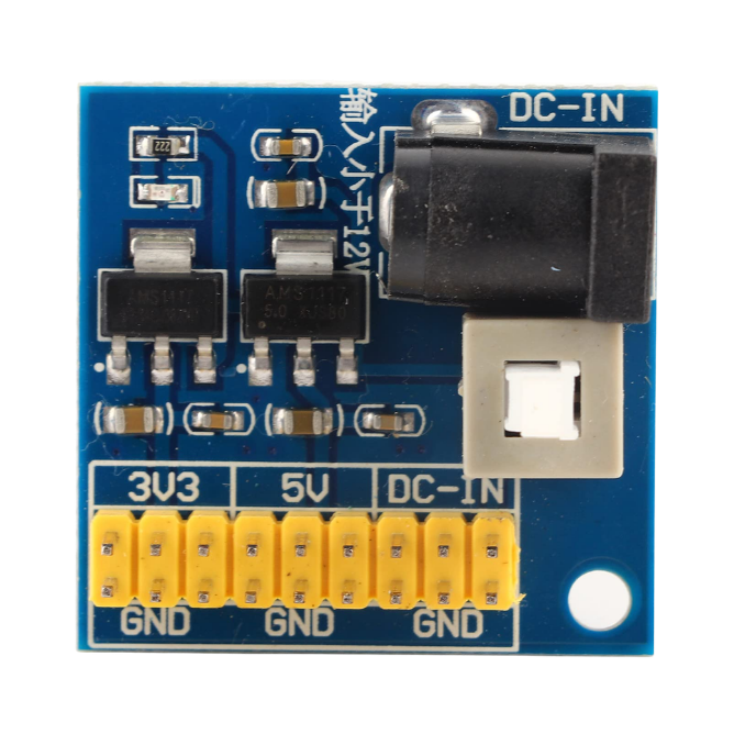
The voltage DC module splitter typically has the following pin or terminal layout:
| Pin/Terminal | Label | Description |
|---|---|---|
| 1 | VIN | Positive DC input voltage |
| 2 | GND | Ground connection for the input voltage |
| 3, 4, 5... | VOUT1, VOUT2, etc. | Positive DC output voltage(s) (same as VIN) |
| 6, 7, 8... | GND | Ground connections for the output voltages |
Usage Instructions
How to Use the Component in a Circuit
Connect the Input Voltage:
- Attach the positive DC voltage source to the
VINterminal. - Connect the ground of the voltage source to the
GNDterminal.
- Attach the positive DC voltage source to the
Connect the Outputs:
- Use the
VOUTterminals to power your devices or modules. - Ensure that the total current drawn by all connected devices does not exceed the module's maximum current rating.
- Use the
Verify Connections:
- Double-check all connections to ensure proper polarity and avoid short circuits.
Power On:
- Turn on the DC power supply and verify that all connected devices are receiving the correct voltage.
Important Considerations and Best Practices
- Current Limitations: Ensure that the total current drawn by all outputs does not exceed the module's maximum current rating. Overloading the module can cause overheating or damage.
- Voltage Compatibility: The input voltage must match the voltage requirements of the connected devices. The module does not regulate or step down/up the voltage.
- Heat Dissipation: If the module is operating near its maximum current capacity, ensure proper ventilation to prevent overheating.
- Polarity Protection: Some modules include built-in polarity protection, but if not, ensure correct polarity to avoid damage.
Example: Using with an Arduino UNO
A voltage DC module splitter can be used to power both an Arduino UNO and additional modules like sensors or relays. Below is an example of how to connect the splitter:
- Connect a 12V DC power supply to the
VINandGNDterminals of the splitter. - Use one
VOUTterminal to power the Arduino UNO via itsVINpin. - Use additional
VOUTterminals to power other modules, ensuring the total current does not exceed the splitter's rating.
Here is an example Arduino code to control a relay module powered by the splitter:
// Example code to control a relay module powered by the DC splitter
const int relayPin = 7; // Pin connected to the relay module

void setup() {
  pinMode(relayPin, OUTPUT); // Set relay pin as output
  digitalWrite(relayPin, LOW); // Ensure relay is off at startup
}

void loop() {
  digitalWrite(relayPin, HIGH); // Turn relay on
  delay(1000); // Wait for 1 second
  digitalWrite(relayPin, LOW); // Turn relay off
  delay(1000); // Wait for 1 second
}
Troubleshooting and FAQs
Common Issues Users Might Face
No Output Voltage:
- Cause: Incorrect input connections or insufficient input voltage.
- Solution: Verify that the input voltage is within the specified range and that the connections are correct.
Overheating:
- Cause: Exceeding the maximum current rating of the module.
- Solution: Reduce the load or use a higher-capacity module.
Voltage Drop at Outputs:
- Cause: High current draw or poor-quality wiring.
- Solution: Use thicker wires and ensure secure connections.
Connected Devices Not Working:
- Cause: Voltage mismatch or insufficient current supply.
- Solution: Verify that the input voltage matches the requirements of the connected devices and that the total current draw is within the module's capacity.
FAQs
Q: Can the module step up or step down the voltage?
A: No, the module only splits the input voltage into multiple outputs. The output voltage is the same as the input voltage.
Q: Can I use this module with an AC power source?
A: No, the module is designed for DC input only. Using an AC source will damage the module.
Q: How many devices can I connect to the splitter?
A: The number of devices depends on the module's number of outputs and the total current draw. Ensure the total current does not exceed the module's maximum rating.
Q: Does the module have built-in protection features?
A: Some modules include features like overcurrent or polarity protection. Check the specific model's datasheet for details.