
How to Use PD 65W module: Examples, Pinouts, and Specs
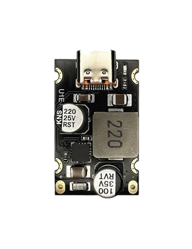
 Design with PD 65W module in Cirkit Designer
Introduction
The PD 65W Module (Manufacturer: Stas, Part ID: 4) is a high-performance Power Delivery (PD) module designed to deliver up to 65 watts of power. It is primarily used in USB-C applications to enable fast charging and efficient power management for a wide range of devices, including smartphones, laptops, tablets, and other USB-C-enabled electronics. This module supports multiple voltage levels, making it versatile for various power delivery requirements.
Explore Projects Built with PD 65W module
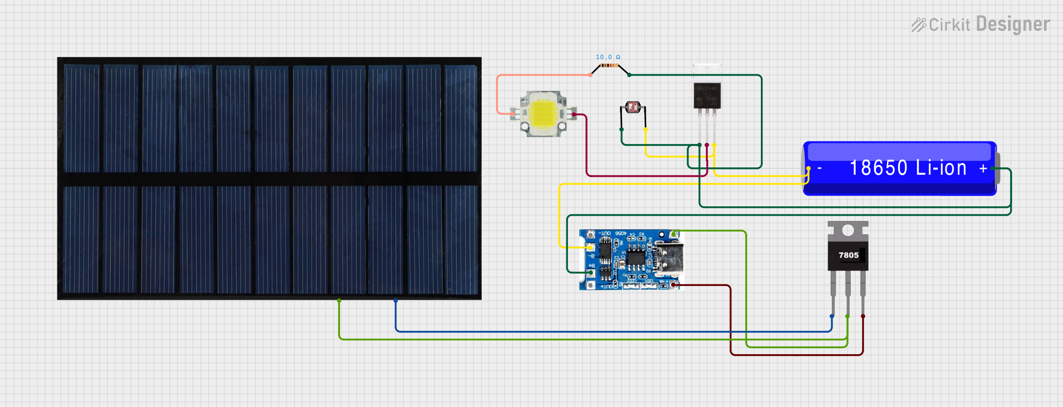 Open Project in Cirkit Designer
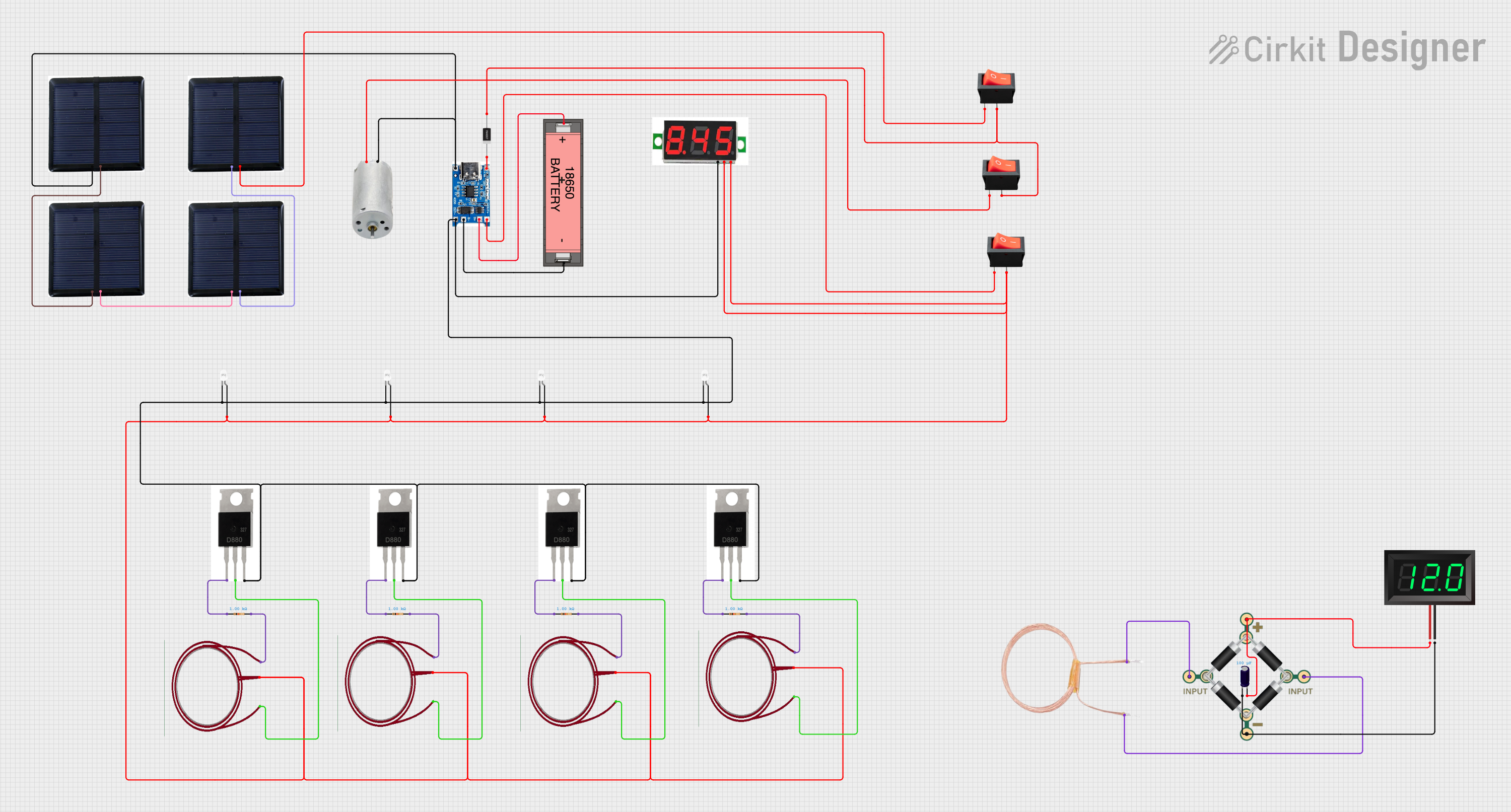 Open Project in Cirkit Designer
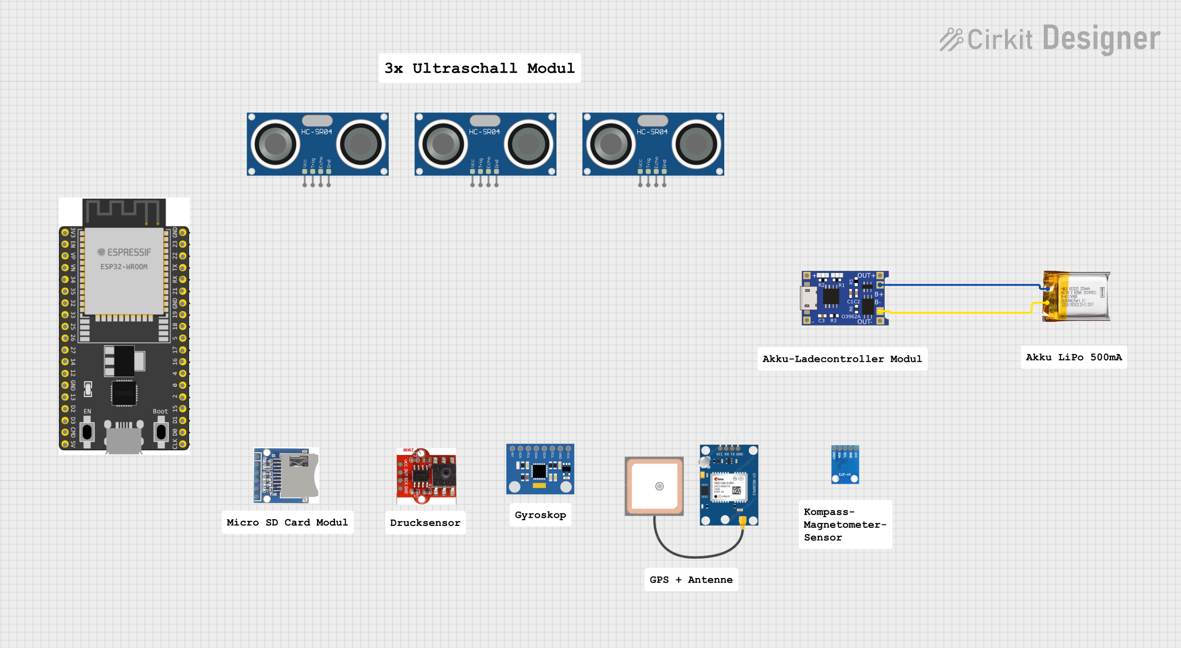 Open Project in Cirkit Designer
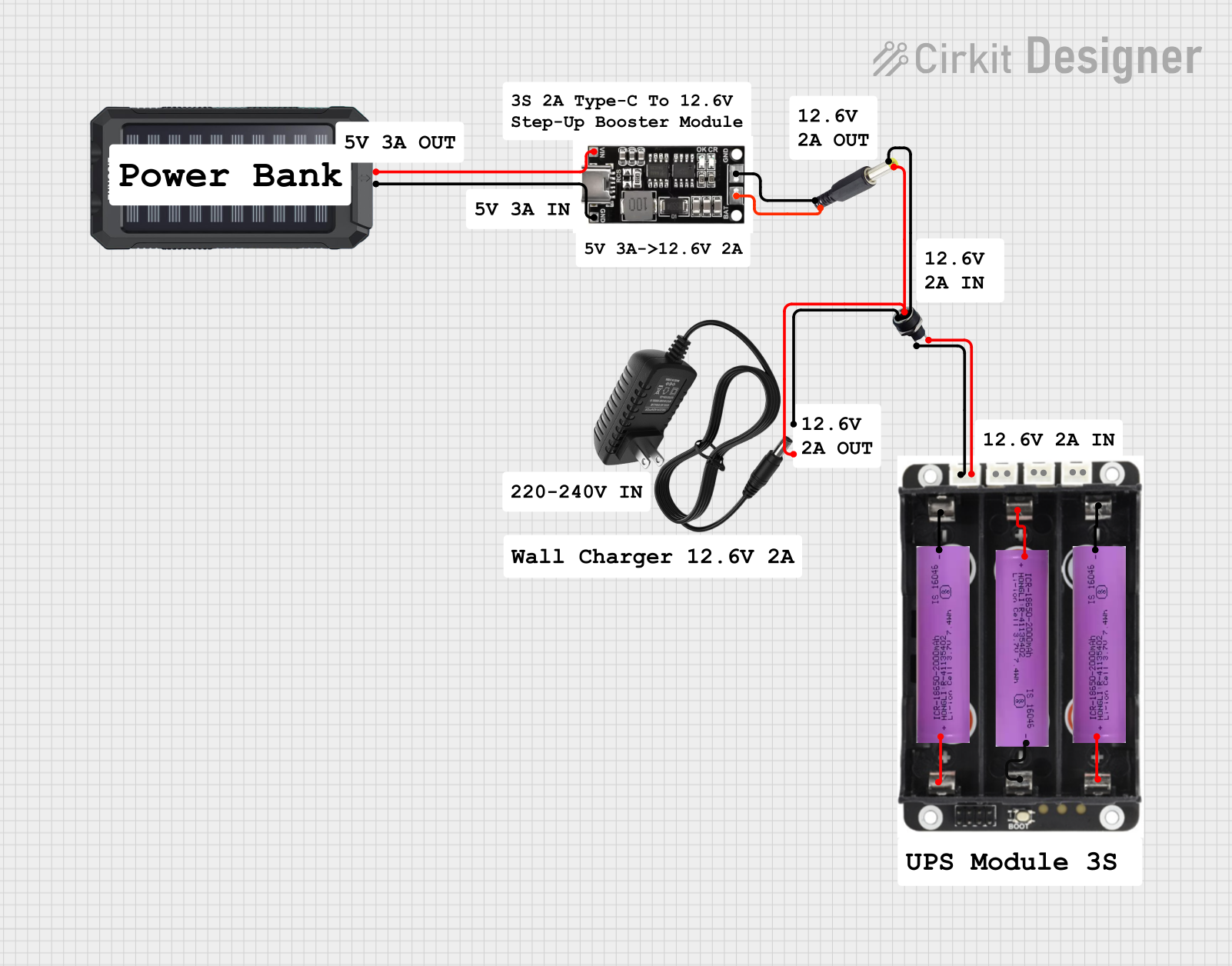 Open Project in Cirkit Designer
Explore Projects Built with PD 65W module
Open Project in Cirkit DesignerOpen Project in Cirkit DesignerOpen Project in Cirkit DesignerOpen Project in Cirkit DesignerCommon Applications
- Fast charging for USB-C devices (e.g., smartphones, laptops, tablets)
- Power management in portable electronics
- Integration into USB-C power adapters and hubs
- DIY projects requiring USB-C power delivery
Technical Specifications
Key Technical Details
| Parameter | Value |
|---|---|
| Input Voltage Range | 100V - 240V AC (via adapter) |
| Output Voltage Levels | 5V, 9V, 12V, 15V, 20V |
| Maximum Output Power | 65W |
| Efficiency | ≥ 92% |
| Communication Protocol | USB Power Delivery (PD 3.0) |
| Operating Temperature | -20°C to 85°C |
| Dimensions | 30mm x 20mm x 10mm |
Pin Configuration and Descriptions
The PD 65W Module has the following pin configuration:
| Pin Number | Pin Name | Description |
|---|---|---|
| 1 | VBUS_IN | Input voltage from the power source (e.g., USB-C adapter) |
| 2 | GND | Ground connection |
| 3 | CC1 | Configuration Channel 1 for USB-C communication |
| 4 | CC2 | Configuration Channel 2 for USB-C communication |
| 5 | VBUS_OUT | Output voltage to the connected device |
| 6 | I2C_SCL | I2C Clock Line for communication with microcontrollers (optional) |
| 7 | I2C_SDA | I2C Data Line for communication with microcontrollers (optional) |
| 8 | STATUS_LED | Output pin to drive an LED for status indication (e.g., power delivery active) |
Usage Instructions
How to Use the PD 65W Module in a Circuit
- Power Input: Connect the input voltage (VBUS_IN) to a compatible USB-C power adapter or power source. Ensure the input voltage is within the specified range (100V - 240V AC via adapter).
- Ground Connection: Connect the GND pin to the ground of your circuit.
- USB-C Communication: Use the CC1 and CC2 pins to establish communication with the connected USB-C device. These pins are essential for negotiating the required voltage and current levels.
- Output Voltage: The module automatically adjusts the output voltage (VBUS_OUT) based on the connected device's requirements, supporting 5V, 9V, 12V, 15V, and 20V.
- Optional I2C Communication: If you need to monitor or control the module via a microcontroller, connect the I2C_SCL and I2C_SDA pins to the corresponding pins on your microcontroller.
- Status LED: Connect an LED to the STATUS_LED pin to visually indicate when power delivery is active.
Important Considerations and Best Practices
- Ensure the power source can supply sufficient current for the desired output power (e.g., 65W requires at least 3.25A at 20V).
- Use proper heat dissipation methods if the module operates at high power levels for extended periods.
- Avoid shorting the VBUS_OUT and GND pins, as this may damage the module.
- For Arduino or other microcontroller integration, ensure the I2C voltage levels are compatible with the module.
Example: Using the PD 65W Module with Arduino UNO
Below is an example of how to monitor the module's status using the I2C interface with an Arduino UNO:
#include <Wire.h> // Include the Wire library for I2C communication

#define MODULE_I2C_ADDRESS 0x3A // Replace with the actual I2C address of the module

void setup() {
  Wire.begin(); // Initialize I2C communication
  Serial.begin(9600); // Start serial communication for debugging

  // Check if the module is connected
  Wire.beginTransmission(MODULE_I2C_ADDRESS);
  if (Wire.endTransmission() == 0) {
    Serial.println("PD 65W Module detected!");
  } else {
    Serial.println("PD 65W Module not detected. Check connections.");
  }
}

void loop() {
  // Request status data from the module
  Wire.beginTransmission(MODULE_I2C_ADDRESS);
  Wire.write(0x01); // Example: Command to request status
  Wire.endTransmission();

  Wire.requestFrom(MODULE_I2C_ADDRESS, 1); // Request 1 byte of data
  if (Wire.available()) {
    byte status = Wire.read();
    if (status == 0x01) {
      Serial.println("Power Delivery Active");
    } else {
      Serial.println("Power Delivery Inactive");
    }
  }

  delay(1000); // Wait 1 second before the next status check
}
Troubleshooting and FAQs
Common Issues and Solutions
Module Not Powering On
- Cause: Insufficient input voltage or current.
- Solution: Verify the input voltage is within the specified range (100V - 240V AC via adapter). Ensure the power source can supply enough current.
Device Not Charging
- Cause: Incorrect connection or unsupported device.
- Solution: Check the CC1 and CC2 connections. Ensure the connected device supports USB Power Delivery.
Overheating
- Cause: Prolonged operation at high power levels without proper cooling.
- Solution: Use a heatsink or active cooling to dissipate heat effectively.
I2C Communication Fails
- Cause: Incorrect wiring or incompatible voltage levels.
- Solution: Verify the I2C connections and ensure the voltage levels match between the module and the microcontroller.
FAQs
Q1: Can the PD 65W Module be used with non-USB-C devices?
A1: No, the module is specifically designed for USB-C applications and requires USB-C communication for proper operation.
Q2: What happens if the connected device requires less than 65W?
A2: The module automatically adjusts the output voltage and current to match the device's requirements.
Q3: Is the module compatible with Quick Charge (QC) devices?
A3: No, the module supports USB Power Delivery (PD) 3.0 and is not compatible with Quick Charge protocols.
Q4: Can I use the module in outdoor environments?
A4: The module is rated for operation between -20°C and 85°C. Ensure it is protected from moisture and extreme conditions when used outdoors.