
How to Use VS1002: Examples, Pinouts, and Specs
 Design with VS1002 in Cirkit Designer
Introduction
The VS1002, manufactured by VLSI Solution, is a high-performance audio decoder chip designed to decode various audio formats, including MP3 and WMA. It is widely used in portable media players, embedded systems, and other audio applications due to its efficient decoding capabilities, low power consumption, and compact design. The chip integrates a digital signal processor (DSP) optimized for audio decoding, making it an ideal choice for applications requiring high-quality audio playback.
Explore Projects Built with VS1002
 Open Project in Cirkit Designer
 Open Project in Cirkit Designer
 Open Project in Cirkit Designer
 Open Project in Cirkit Designer
Explore Projects Built with VS1002
Open Project in Cirkit DesignerOpen Project in Cirkit DesignerOpen Project in Cirkit DesignerOpen Project in Cirkit DesignerCommon Applications
- Portable media players
- Embedded audio systems
- Audio streaming devices
- Automotive audio systems
- Home audio equipment
Technical Specifications
Key Technical Details
| Parameter | Value |
|---|---|
| Supported Audio Formats | MP3, WMA, WAV, Ogg Vorbis |
| Supply Voltage | 2.7V to 3.6V |
| Operating Current | 15-30 mA (typical, depending on workload) |
| Clock Frequency | 12.288 MHz |
| Audio Output | Stereo, 16-bit DAC |
| Input Interface | Serial (SPI) |
| Output Interface | Stereo audio line out |
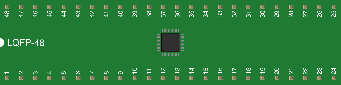
| Package Type | LQFP-48 |
Pin Configuration and Descriptions
The VS1002 comes in a 48-pin LQFP package. Below is a summary of the key pins and their functions:
| Pin Number | Pin Name | Description |
|---|---|---|
| 1 | VDD | Core supply voltage (2.7V to 3.6V) |
| 2 | GND | Ground |
| 3 | RX | Serial data input for audio stream |
| 4 | TX | Serial data output |
| 5 | SCLK | SPI clock input |
| 6 | SDI | SPI data input |
| 7 | XRESET | Hardware reset input |
| 8 | DREQ | Data request signal (indicates readiness) |
| 9 | LEFT | Left audio output |
| 10 | RIGHT | Right audio output |
| 11 | XTALI | Crystal oscillator input |
| 12 | XTALO | Crystal oscillator output |
For a complete pinout, refer to the VS1002 datasheet provided by VLSI Solution.
Usage Instructions
How to Use the VS1002 in a Circuit
- Power Supply: Connect the VDD pin to a regulated 3.3V power supply and GND to ground.
- Clock Source: Attach a 12.288 MHz crystal oscillator to the XTALI and XTALO pins.
- SPI Communication: Use the SDI, SCLK, and DREQ pins to interface with a microcontroller or host device via SPI. Ensure proper pull-up resistors are used if required.
- Audio Input: Send audio data to the RX pin using the SPI interface.
- Audio Output: Connect the LEFT and RIGHT pins to an audio amplifier or headphones for stereo output.
- Reset: Use the XRESET pin to initialize the chip during startup or after a fault.
Important Considerations
- Decoupling Capacitors: Place decoupling capacitors (e.g., 0.1 µF) close to the power supply pins to reduce noise.
- Audio Quality: Use high-quality components for the audio output stage to ensure optimal sound quality.
- SPI Speed: Configure the SPI clock speed according to the VS1002's specifications to avoid data corruption.
- Heat Dissipation: Ensure proper ventilation or heat sinking if the chip operates in a high-temperature environment.
Example Code for Arduino UNO
Below is an example of how to interface the VS1002 with an Arduino UNO to play an MP3 file:
#include <SPI.h>

// Pin definitions
#define VS1002_CS 10    // Chip Select pin
#define VS1002_DREQ 9   // Data Request pin
#define VS1002_RST 8    // Reset pin

void setup() {
  // Initialize SPI
  SPI.begin();
  pinMode(VS1002_CS, OUTPUT);
  pinMode(VS1002_DREQ, INPUT);
  pinMode(VS1002_RST, OUTPUT);

  // Reset the VS1002
  digitalWrite(VS1002_RST, LOW);
  delay(100); // Wait for reset
  digitalWrite(VS1002_RST, HIGH);

  // Configure VS1002 (example: set volume)
  setVolume(0x20, 0x20); // Left and right channel volume
}

void loop() {
  // Check if VS1002 is ready for data
  if (digitalRead(VS1002_DREQ) == HIGH) {
    // Send audio data to VS1002
    sendAudioData();
  }
}

void setVolume(uint8_t left, uint8_t right) {
  // Send volume control command to VS1002
  digitalWrite(VS1002_CS, LOW);
  SPI.transfer(0x02); // Write command
  SPI.transfer(0x0B); // Volume register address
  SPI.transfer(left); // Left channel volume
  SPI.transfer(right); // Right channel volume
  digitalWrite(VS1002_CS, HIGH);
}

void sendAudioData() {
  // Example function to send audio data
  // Replace with actual audio data transmission logic
  digitalWrite(VS1002_CS, LOW);
  SPI.transfer(0xFF); // Dummy audio data
  digitalWrite(VS1002_CS, HIGH);
}
Notes:
- Ensure the MP3 file is preprocessed and sent in chunks compatible with the VS1002.
- Modify the
sendAudioData()function to read and send actual MP3 data from an SD card or other storage.
Troubleshooting and FAQs
Common Issues
No Audio Output:
- Verify the power supply voltage is within the specified range (2.7V to 3.6V).
- Check the connections to the LEFT and RIGHT audio output pins.
- Ensure the audio data is being sent correctly via SPI.
Chip Not Responding:
- Confirm the XRESET pin is properly toggled during initialization.
- Check the SPI connections and ensure the clock speed is within the supported range.
Distorted Audio:
- Verify the decoupling capacitors are correctly placed near the power pins.
- Check the audio output stage for proper impedance matching.
Tips for Troubleshooting
- Use an oscilloscope to monitor the SPI signals and ensure proper communication.
- Test the DREQ pin to confirm the chip is ready to receive data.
- Refer to the VS1002 datasheet for detailed timing diagrams and register configurations.
FAQs
Q: Can the VS1002 decode other formats like AAC?
A: No, the VS1002 supports MP3, WMA, WAV, and Ogg Vorbis formats only.
Q: What is the maximum SPI clock speed supported?
A: The VS1002 supports SPI clock speeds up to 5 MHz.
Q: Can I use the VS1002 with a 5V microcontroller?
A: Yes, but you must use level shifters to convert the 5V logic to 3.3V for the VS1002.
Q: Is an external amplifier required for audio output?
A: Yes, the VS1002 provides line-level audio output, so an external amplifier is recommended for driving speakers.