How to Use mkem0002_button_module: Examples, Pinouts, and Specs
Introduction
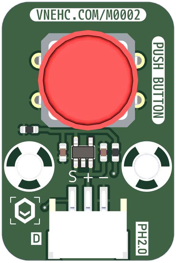
The MKEM0002 Button Module, manufactured by MKEVN, is a versatile and user-friendly component designed for seamless integration into electronic projects. This module simplifies the process of adding tactile input to your designs, making it ideal for creating user interfaces that respond to button presses. Its compact design and straightforward functionality make it suitable for both beginners and experienced developers.
Explore Projects Built with mkem0002_button_module

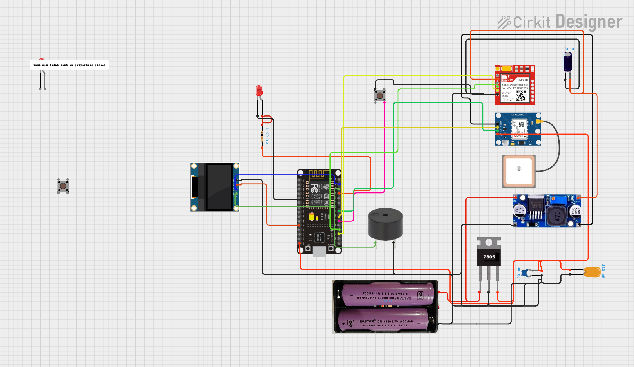

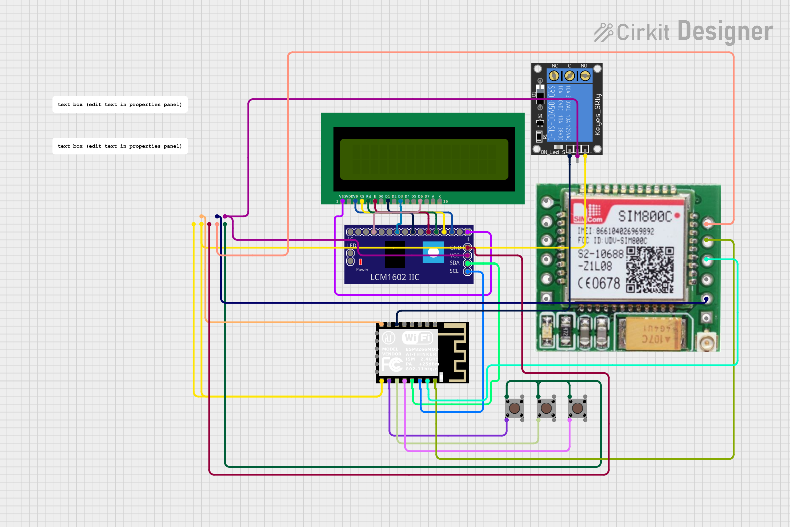
Explore Projects Built with mkem0002_button_module
Common Applications and Use Cases
- Microcontroller Projects: Use the button module to trigger actions or events in Arduino, Raspberry Pi, or other microcontroller-based systems.
- User Interfaces: Integrate the module into devices requiring simple input mechanisms, such as menu navigation or mode selection.
- Prototyping: Ideal for rapid prototyping of interactive systems.
- Educational Projects: A great tool for teaching basic electronics and programming concepts.
Technical Specifications
The MKEM0002 Button Module is designed to operate reliably in a wide range of applications. Below are its key technical details:
Key Technical Details
| Parameter | Value |
|---|---|
| Operating Voltage | 3.3V to 5V |
| Maximum Current | 10mA |
| Button Type | Momentary (Normally Open) |
| Debouncing Circuit | No (external debouncing may be required) |
| Dimensions | 12mm x 12mm x 8mm |
| Mounting Type | PCB Mount or Breadboard Compatible |
Pin Configuration and Descriptions
The MKEM0002 Button Module has a simple 3-pin configuration:
| Pin Number | Pin Name | Description |
|---|---|---|
| 1 | VCC | Connect to the positive supply voltage (3.3V-5V). |
| 2 | GND | Connect to the ground of the circuit. |
| 3 | OUT | Outputs a HIGH signal when the button is pressed, and LOW when released. |
Usage Instructions
The MKEM0002 Button Module is straightforward to use in a circuit. Follow the steps below to integrate it into your project:
How to Use the Component in a Circuit
Connect the Pins:
- Connect the VCC pin to the 3.3V or 5V power supply of your system.
- Connect the GND pin to the ground of your circuit.
- Connect the OUT pin to a digital input pin of your microcontroller or other logic circuit.
Pull-Down Resistor:
- Since the module does not include a built-in pull-down resistor, it is recommended to add a 10kΩ resistor between the OUT pin and GND to ensure a stable LOW signal when the button is not pressed.
Debouncing:
- The button does not include a hardware debouncing circuit. Implement software debouncing in your microcontroller code to avoid false triggers caused by mechanical bouncing.
Example: Using with Arduino UNO
Below is an example of how to use the MKEM0002 Button Module with an Arduino UNO:
// Define the pin connected to the button module's OUT pin
const int buttonPin = 2; // Digital pin 2
const int ledPin = 13;   // Built-in LED pin

// Variable to store the button state
int buttonState = 0;

void setup() {
  pinMode(buttonPin, INPUT); // Set button pin as input
  pinMode(ledPin, OUTPUT);   // Set LED pin as output
  Serial.begin(9600);        // Initialize serial communication
}

void loop() {
  // Read the button state
  buttonState = digitalRead(buttonPin);

  // Check if the button is pressed
  if (buttonState == HIGH) {
    digitalWrite(ledPin, HIGH); // Turn on the LED
    Serial.println("Button Pressed!"); // Print message to serial monitor
  } else {
    digitalWrite(ledPin, LOW); // Turn off the LED
  }

  delay(50); // Add a small delay for stability
}
Important Considerations and Best Practices
- Voltage Compatibility: Ensure the module is powered within its operating voltage range (3.3V to 5V).
- Debouncing: Always implement debouncing (either in hardware or software) to avoid erratic behavior.
- Pull-Down Resistor: Use a pull-down resistor to maintain a stable LOW state when the button is not pressed.
- Avoid Overcurrent: Do not exceed the maximum current rating of 10mA to prevent damage to the module.
Troubleshooting and FAQs
Common Issues and Solutions
Button Press Not Detected:
- Cause: Missing pull-down resistor.
- Solution: Add a 10kΩ pull-down resistor between the OUT pin and GND.
Erratic Behavior When Pressing the Button:
- Cause: Mechanical bouncing of the button.
- Solution: Implement software debouncing in your microcontroller code.
No Output Signal:
- Cause: Incorrect wiring or insufficient power supply.
- Solution: Double-check the connections and ensure the module is powered within the specified voltage range.
Output Always HIGH or LOW:
- Cause: Faulty module or incorrect pull-down resistor value.
- Solution: Test the module with a multimeter and verify the resistor value.
FAQs
Q1: Can I use the MKEM0002 Button Module with a 3.3V microcontroller?
A1: Yes, the module is compatible with both 3.3V and 5V systems.
Q2: Does the module include an onboard LED to indicate button presses?
A2: No, the module does not include an onboard LED. You can connect an external LED to visualize button presses.
Q3: Can I use multiple MKEM0002 modules in the same circuit?
A3: Yes, you can use multiple modules. Ensure each module is connected to a separate input pin on your microcontroller.
Q4: Is the module suitable for high-frequency switching applications?
A4: No, the module is designed for low-frequency tactile input and may not perform well in high-frequency applications.
By following this documentation, you can effectively integrate the MKEM0002 Button Module into your projects and troubleshoot any issues that arise.