
How to Use AD5206 Digital Potentiometer: Examples, Pinouts, and Specs
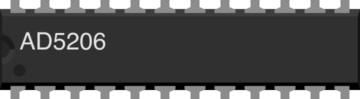
 Design with AD5206 Digital Potentiometer in Cirkit Designer
Introduction
The AD5206 is a digital potentiometer manufactured by Analog Devices. It features a 256-position resolution, allowing for precise adjustment of resistance in electronic circuits. The device is controlled via a 2-wire SPI (Serial Peripheral Interface) communication protocol, making it easy to integrate into microcontroller-based systems.
This component is ideal for applications requiring variable resistance, such as:
- Audio volume control
- Sensor calibration
- Adjustable gain amplifiers
- LED dimming
- Programmable power supplies
The AD5206 provides six independent potentiometer channels, making it a versatile solution for multi-channel applications.
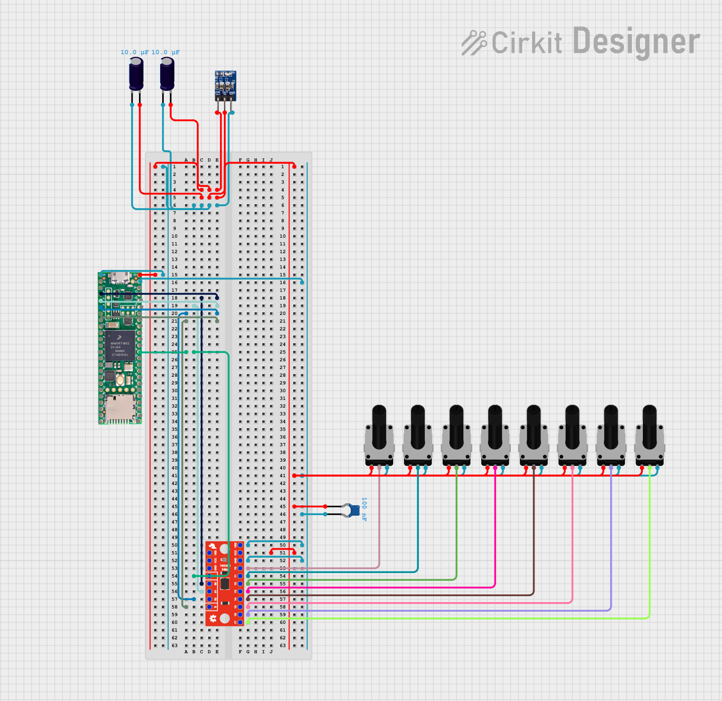
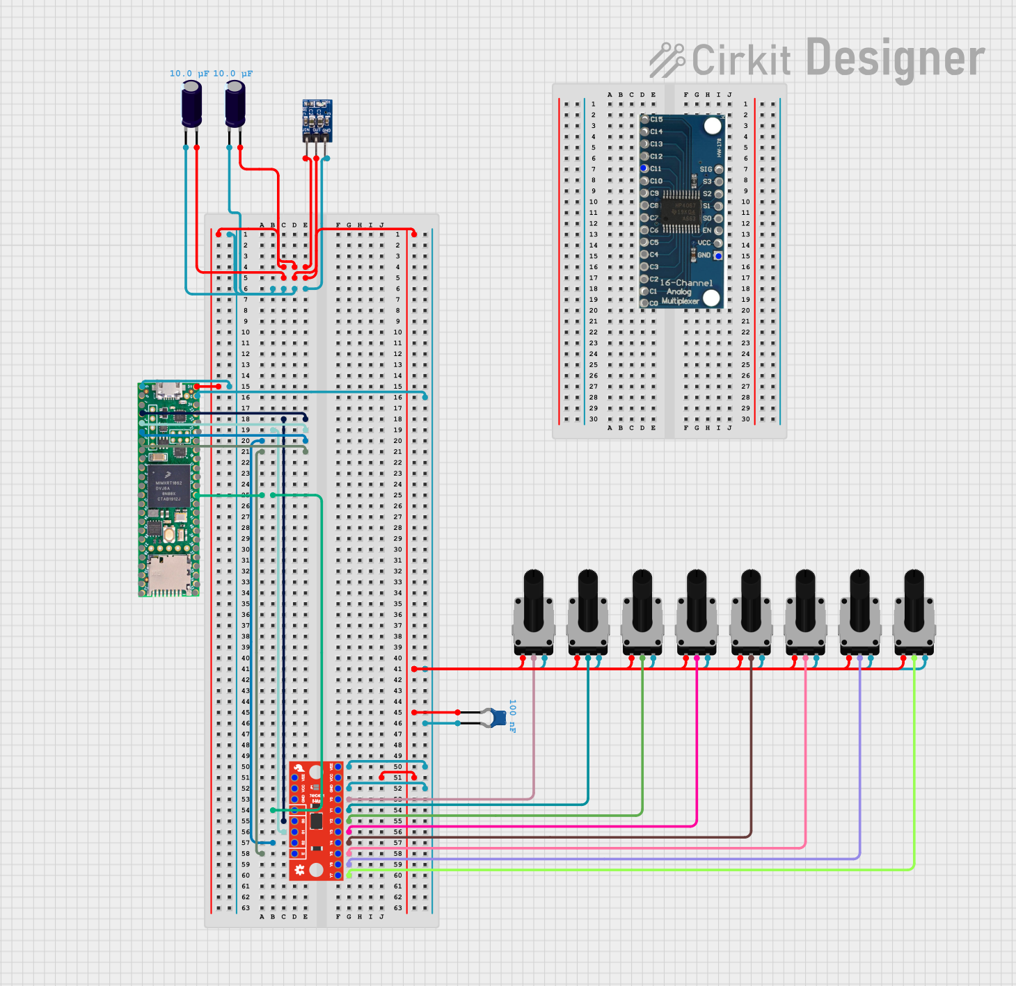
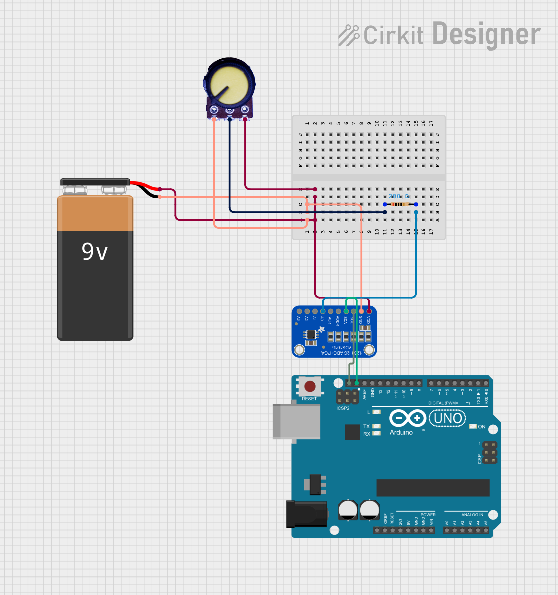
Explore Projects Built with AD5206 Digital Potentiometer
 Open Project in Cirkit Designer
 Open Project in Cirkit Designer
 Open Project in Cirkit Designer
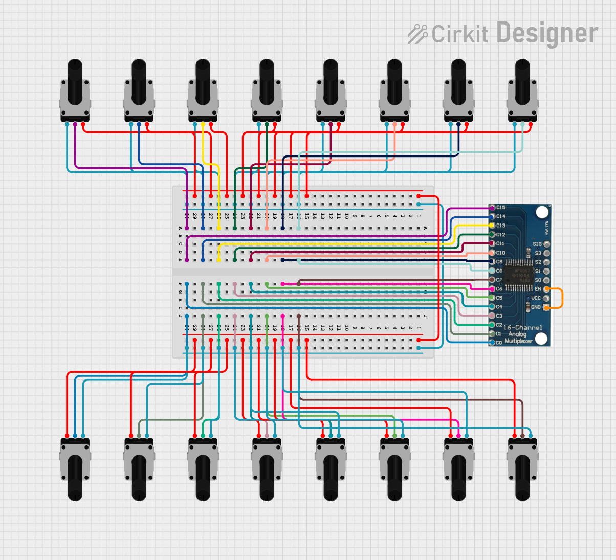 Open Project in Cirkit Designer
Explore Projects Built with AD5206 Digital Potentiometer
Open Project in Cirkit DesignerOpen Project in Cirkit DesignerOpen Project in Cirkit DesignerOpen Project in Cirkit DesignerTechnical Specifications
Key Technical Details
| Parameter | Value |
|---|---|
| Manufacturer | Analog Devices |
| Part Number | AD5206 |
| Number of Channels | 6 |
| Resolution | 256 positions (8-bit) |
| Resistance Options | 10 kΩ, 50 kΩ, 100 kΩ |
| Supply Voltage (VDD) | 2.7 V to 5.5 V |
| Communication Protocol | SPI |
| Operating Temperature Range | -40°C to +85°C |
| Package Options | 20-lead PDIP, SOIC, TSSOP |
Pin Configuration and Descriptions
The AD5206 comes in a 20-pin package. Below is the pinout and description:
| Pin Number | Pin Name | Description |
|---|---|---|
| 1 | A1 | Terminal A of potentiometer 1 |
| 2 | W1 | Wiper terminal of potentiometer 1 |
| 3 | B1 | Terminal B of potentiometer 1 |
| 4 | A2 | Terminal A of potentiometer 2 |
| 5 | W2 | Wiper terminal of potentiometer 2 |
| 6 | B2 | Terminal B of potentiometer 2 |
| 7 | A3 | Terminal A of potentiometer 3 |
| 8 | W3 | Wiper terminal of potentiometer 3 |
| 9 | B3 | Terminal B of potentiometer 3 |
| 10 | GND | Ground |
| 11 | CS | Chip Select (active low) |
| 12 | SDI | Serial Data Input |
| 13 | CLK | Serial Clock Input |
| 14 | SDO | Serial Data Output |
| 15 | A4 | Terminal A of potentiometer 4 |
| 16 | W4 | Wiper terminal of potentiometer 4 |
| 17 | B4 | Terminal B of potentiometer 4 |
| 18 | A5 | Terminal A of potentiometer 5 |
| 19 | W5 | Wiper terminal of potentiometer 5 |
| 20 | B5 | Terminal B of potentiometer 5 |
Usage Instructions
How to Use the AD5206 in a Circuit
- Power Supply: Connect the VDD pin to a 2.7 V to 5.5 V power source and the GND pin to ground.
- SPI Communication:
- Connect the CS pin to a GPIO pin on your microcontroller to enable/disable the device.
- Connect the SDI pin to the MOSI (Master Out Slave In) pin of your microcontroller.
- Connect the CLK pin to the SPI clock pin of your microcontroller.
- Optionally, connect the SDO pin to the MISO (Master In Slave Out) pin if you need to read data back.
- Potentiometer Terminals: Connect the A, B, and W terminals of each potentiometer to your circuit as needed.
- Programming the Wiper Position:
- Send an 8-bit command via SPI to set the wiper position for a specific channel.
- The command format is:
[Channel Address (3 bits)] [Wiper Position (8 bits)].
Example Arduino Code
Below is an example of how to control the AD5206 using an Arduino UNO:
#include <SPI.h>

// Define SPI pins
const int CS_PIN = 10; // Chip Select pin

void setup() {
  pinMode(CS_PIN, OUTPUT);
  digitalWrite(CS_PIN, HIGH); // Ensure CS is inactive
  SPI.begin(); // Initialize SPI
}

void loop() {
  setWiperPosition(0, 128); // Set channel 0 to mid-scale (128/256)
  delay(1000); // Wait for 1 second
  setWiperPosition(0, 255); // Set channel 0 to max-scale (255/256)
  delay(1000); // Wait for 1 second
}

// Function to set the wiper position of a specific channel
void setWiperPosition(byte channel, byte position) {
  digitalWrite(CS_PIN, LOW); // Activate the AD5206
  SPI.transfer(channel); // Send the channel address
  SPI.transfer(position); // Send the wiper position
  digitalWrite(CS_PIN, HIGH); // Deactivate the AD5206
}
Important Considerations and Best Practices
- Power Supply: Ensure the supply voltage (VDD) is within the specified range (2.7 V to 5.5 V).
- SPI Timing: Follow the SPI timing requirements specified in the datasheet to avoid communication errors.
- Unused Channels: If any potentiometer channels are unused, leave their terminals unconnected.
- ESD Protection: Handle the device with care to prevent electrostatic discharge (ESD) damage.
Troubleshooting and FAQs
Common Issues and Solutions
No Response from the AD5206:
- Ensure the CS pin is properly toggled (active low) during SPI communication.
- Verify the SPI clock frequency is within the supported range.
Incorrect Wiper Position:
- Double-check the SPI command format and ensure the correct channel address and wiper position are sent.
- Verify the connections to the SDI and CLK pins.
Device Overheating:
- Ensure the total power dissipation does not exceed the device's maximum rating.
- Check for short circuits in the potentiometer terminals.
FAQs
Q: Can I use the AD5206 with a 3.3 V microcontroller?
A: Yes, the AD5206 supports a supply voltage range of 2.7 V to 5.5 V, making it compatible with 3.3 V systems.
Q: How many channels can I control simultaneously?
A: The AD5206 has six independent potentiometer channels, and each can be controlled individually.
Q: Is the wiper position retained after power-off?
A: No, the wiper position is not non-volatile and will reset to its default state upon power-up.
Q: Can I daisy-chain multiple AD5206 devices?
A: Yes, the AD5206 supports daisy-chaining via the SDO pin for cascading multiple devices.
This concludes the documentation for the AD5206 Digital Potentiometer. For further details, refer to the official datasheet provided by Analog Devices.