How to Use PWM to DAC Converter: Examples, Pinouts, and Specs
Introduction
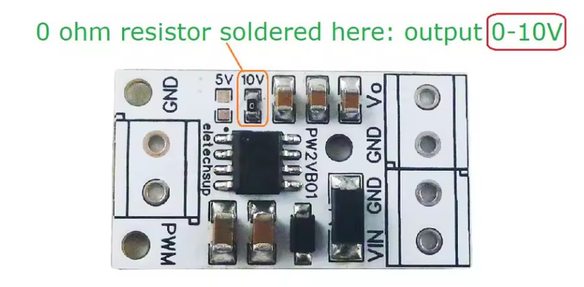
A PWM to DAC Converter is a device that converts Pulse Width Modulation (PWM) signals into a corresponding analog voltage output. Manufactured by AliExpress (Part ID: 0-10V no pin), this component is widely used in applications where digital signals need to be translated into analog signals for control purposes.
Common applications include:
- Audio systems for generating analog audio signals from digital sources.
- Motor control systems to regulate speed or torque using analog voltage.
- Signal processing in industrial automation and control systems.
- Interfacing microcontrollers with analog devices.
This converter is particularly useful in scenarios where microcontrollers or other digital devices output PWM signals but the target device requires an analog voltage input.
Explore Projects Built with PWM to DAC Converter

Explore Projects Built with PWM to DAC Converter
Technical Specifications
Below are the key technical details of the PWM to DAC Converter:
| Parameter | Specification |
|---|---|
| Input Voltage Range | 12V to 24V DC |
| PWM Input Frequency | 1 kHz to 3 kHz |
| PWM Duty Cycle Range | 0% to 100% |
| Output Voltage Range | 0V to 10V DC |
| Output Current | Max 10 mA |
| Accuracy | ±1% |
| Operating Temperature | -20°C to 60°C |
| Dimensions | 50mm x 30mm x 15mm |
Pin Configuration and Descriptions
The PWM to DAC Converter has the following pin configuration:
| Pin Name | Description |
|---|---|
| VCC | Power supply input (12V to 24V DC) |
| GND | Ground connection |
| PWM IN | PWM signal input (1 kHz to 3 kHz, 0% to 100% duty) |
| VOUT | Analog voltage output (0V to 10V DC) |
Usage Instructions
How to Use the Component in a Circuit
- Power Supply: Connect the VCC pin to a DC power source (12V to 24V) and the GND pin to the ground of the power source.
- PWM Input: Connect the PWM signal from your microcontroller or other digital device to the PWM IN pin. Ensure the PWM frequency is within the supported range (1 kHz to 3 kHz).
- Analog Output: The VOUT pin will output a voltage proportional to the duty cycle of the PWM signal. For example:
- 0% duty cycle → 0V output
- 50% duty cycle → 5V output
- 100% duty cycle → 10V output
- Load Connection: Connect the VOUT pin to the input of the analog device you wish to control. Ensure the load does not exceed the maximum output current of 10 mA.
Important Considerations and Best Practices
- PWM Signal Quality: Use a stable and noise-free PWM signal for accurate conversion. Unstable signals may result in fluctuating output voltage.
- Frequency Range: Ensure the PWM frequency is within the specified range (1 kHz to 3 kHz). Frequencies outside this range may cause incorrect output.
- Output Load: Do not connect a load that exceeds the maximum output current (10 mA). Use a buffer circuit if higher current is required.
- Heat Dissipation: Operate the converter within the specified temperature range (-20°C to 60°C) to avoid overheating.
Example: Using with Arduino UNO
Below is an example of how to use the PWM to DAC Converter with an Arduino UNO to generate a 0V to 10V analog output.
// Example: Controlling a PWM to DAC Converter with Arduino UNO
// This code generates a PWM signal on pin 9 with a duty cycle proportional
// to the value of a potentiometer connected to A0.

const int pwmPin = 9;       // PWM output pin
const int potPin = A0;      // Potentiometer input pin

void setup() {
  pinMode(pwmPin, OUTPUT);  // Set PWM pin as output
}

void loop() {
  int potValue = analogRead(potPin);  // Read potentiometer value (0-1023)
  int pwmValue = map(potValue, 0, 1023, 0, 255); // Map to PWM range (0-255)

  analogWrite(pwmPin, pwmValue);  // Output PWM signal
  delay(10);  // Small delay for stability
}
In this example:
- A potentiometer is used to control the duty cycle of the PWM signal.
- The PWM signal is sent to the PWM IN pin of the converter.
- The VOUT pin of the converter outputs a corresponding analog voltage (0V to 10V).
Troubleshooting and FAQs
Common Issues and Solutions
No Output Voltage
- Cause: No PWM signal or incorrect connection.
- Solution: Verify the PWM signal is present and properly connected to the PWM IN pin. Check the power supply connections.
Fluctuating Output Voltage
- Cause: Unstable PWM signal or noise interference.
- Solution: Use a decoupling capacitor near the PWM IN pin to filter noise. Ensure the PWM source is stable.
Output Voltage Not Matching Duty Cycle
- Cause: PWM frequency is outside the supported range.
- Solution: Adjust the PWM frequency to be within 1 kHz to 3 kHz.
Overheating
- Cause: Operating outside the specified temperature range or excessive load.
- Solution: Ensure proper ventilation and reduce the load on the VOUT pin.
FAQs
Q: Can I use this converter with a 5V PWM signal?
A: Yes, the converter is compatible with 5V PWM signals. Ensure the frequency and duty cycle are within the specified range.
Q: What happens if the PWM frequency is too low or too high?
A: Frequencies outside the 1 kHz to 3 kHz range may result in inaccurate or unstable output voltage.
Q: Can I connect multiple devices to the VOUT pin?
A: Yes, but ensure the total current draw does not exceed 10 mA. Use a buffer circuit if higher current is required.
Q: Is the output voltage linear with respect to the duty cycle?
A: Yes, the output voltage is linearly proportional to the PWM duty cycle.
By following this documentation, you can effectively integrate the PWM to DAC Converter into your projects and troubleshoot common issues.