
How to Use PSP_CONNECTOR: Examples, Pinouts, and Specs

 Design with PSP_CONNECTOR in Cirkit Designer
Introduction
The PSP connector is a specialized electrical connector designed for interfacing with PlayStation Portable (PSP) devices. It facilitates both power delivery and data transfer, making it an essential component for charging, syncing, and communication between the PSP and other devices. Its compact design and reliable performance make it a popular choice for gaming enthusiasts and developers working with PSP hardware.
Explore Projects Built with PSP_CONNECTOR
 Open Project in Cirkit Designer
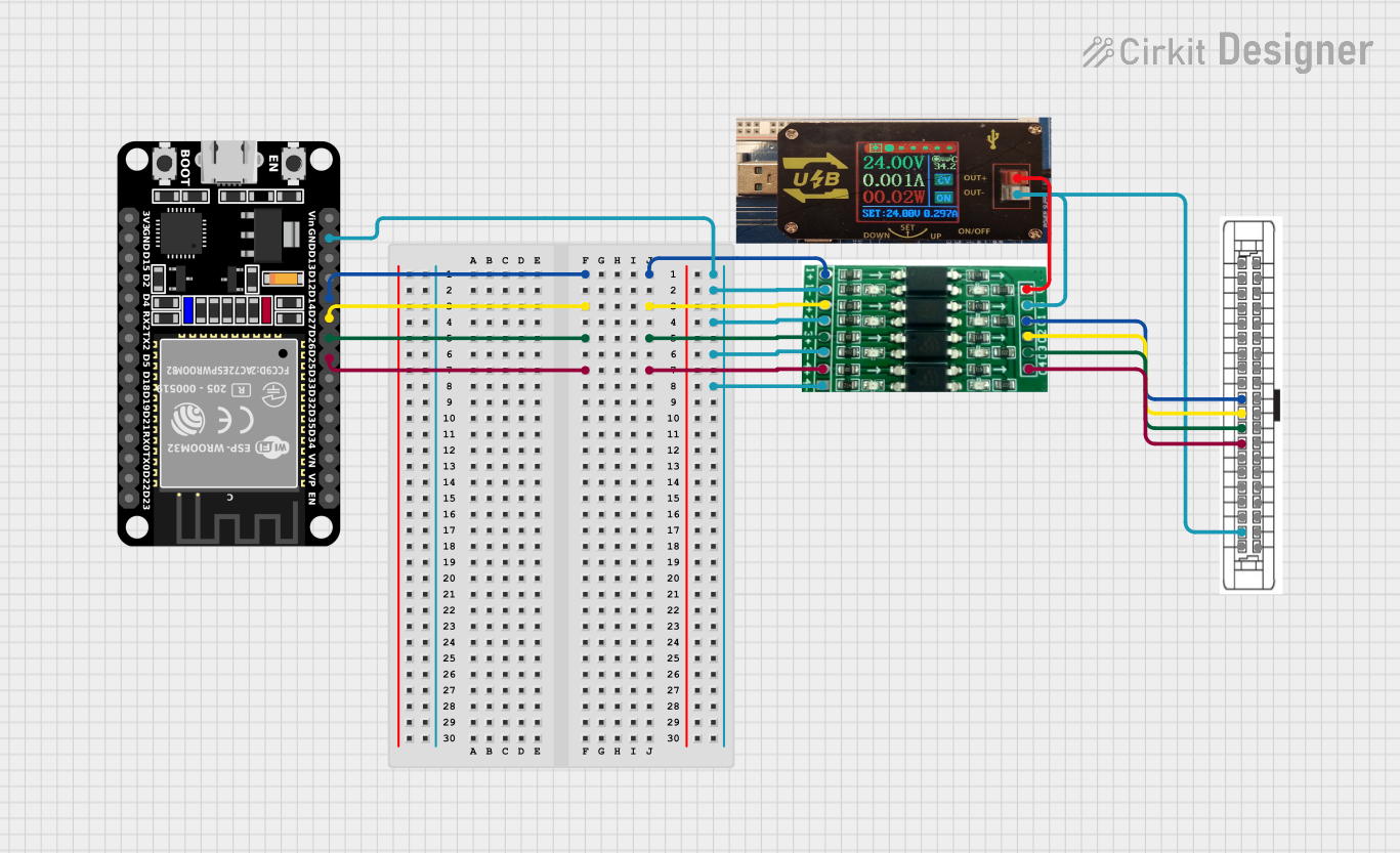 Open Project in Cirkit Designer
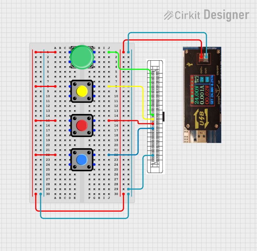 Open Project in Cirkit Designer
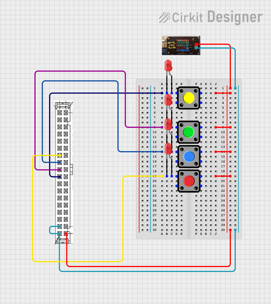 Open Project in Cirkit Designer
Explore Projects Built with PSP_CONNECTOR
Open Project in Cirkit DesignerOpen Project in Cirkit DesignerOpen Project in Cirkit DesignerOpen Project in Cirkit DesignerCommon Applications and Use Cases
- Charging PSP devices using external power sources.
- Transferring data between PSP devices and computers.
- Integrating PSP devices into custom electronic projects.
- Repairing or replacing damaged PSP connectors in gaming consoles.
Technical Specifications
Key Technical Details
- Connector Type: Proprietary PSP interface
- Voltage Rating: 5V DC (standard USB power)
- Current Rating: Up to 2A
- Data Protocol: USB 2.0 (for data transfer)
- Operating Temperature: -10°C to 60°C
- Durability: Rated for 10,000 mating cycles
Pin Configuration and Descriptions
The PSP connector typically consists of 5 pins, each serving a specific function. Below is the pinout configuration:
| Pin Number | Name | Description |
|---|---|---|
| 1 | VCC (+5V) | Supplies power to the PSP device. |
| 2 | D- (Data -) | Negative data line for USB communication. |
| 3 | D+ (Data +) | Positive data line for USB communication. |
| 4 | ID (Identifier) | Used for device identification or accessory detection. |
| 5 | GND (Ground) | Provides the ground connection for power and data signals. |
Usage Instructions
How to Use the PSP Connector in a Circuit
- Power Supply: Connect the VCC pin to a regulated 5V DC power source. Ensure the power supply can provide sufficient current (up to 2A) for the PSP device.
- Data Transfer: Connect the D+ and D- pins to the corresponding data lines of a USB interface for communication with a computer or other devices.
- Grounding: Ensure the GND pin is properly connected to the circuit's ground to complete the power and data pathways.
- Device Identification: If required, use the ID pin for accessory detection or custom functionality.
Important Considerations and Best Practices
- Voltage Regulation: Always use a regulated 5V power source to avoid damaging the PSP device.
- Pin Alignment: Double-check the pin alignment before connecting the PSP connector to avoid short circuits or incorrect connections.
- Cable Quality: Use high-quality cables to ensure reliable power delivery and data transfer.
- Heat Management: Avoid prolonged use in high-temperature environments to prevent overheating.
Example: Connecting to an Arduino UNO
The PSP connector can be used with an Arduino UNO for custom projects, such as controlling the PSP or reading data. Below is an example code snippet for basic serial communication:
// Example: Communicating with a PSP device using Arduino UNO
// Ensure proper connections: D+ to Arduino RX, D- to Arduino TX, GND to Arduino GND

#include <SoftwareSerial.h>

// Define RX and TX pins for SoftwareSerial
SoftwareSerial PSPSerial(10, 11); // RX = Pin 10, TX = Pin 11

void setup() {
  // Initialize serial communication with PSP device
  PSPSerial.begin(9600); // Set baud rate to 9600
  Serial.begin(9600);    // For debugging via Serial Monitor

  Serial.println("PSP Connector Communication Initialized");
}

void loop() {
  // Check if data is available from PSP
  if (PSPSerial.available()) {
    char data = PSPSerial.read(); // Read data from PSP
    Serial.print("Received: ");
    Serial.println(data);         // Print received data to Serial Monitor
  }

  // Send data to PSP (example: sending 'A')
  PSPSerial.write('A');
  delay(1000); // Wait 1 second before sending again
}
Troubleshooting and FAQs
Common Issues and Solutions
No Power to PSP Device
- Cause: Incorrect connection to the VCC or GND pins.
- Solution: Verify the power supply and ensure proper pin alignment.
Data Transfer Fails
- Cause: Faulty cable or incorrect D+ and D- connections.
- Solution: Use a high-quality USB cable and confirm the data lines are correctly connected.
Overheating
- Cause: Excessive current draw or poor ventilation.
- Solution: Ensure the power source is within the specified current rating and improve airflow around the connector.
Device Not Recognized
- Cause: Missing or incorrect connection to the ID pin.
- Solution: Check the ID pin configuration and ensure it matches the PSP device's requirements.
FAQs
Can I use a standard USB connector instead of a PSP connector?
- No, the PSP connector is proprietary and designed specifically for PSP devices. A standard USB connector will not fit or function correctly.
What is the maximum cable length for reliable data transfer?
- For USB 2.0, the maximum recommended cable length is 5 meters to maintain signal integrity.
Is the PSP connector compatible with all PSP models?
- Most PSP models use the same connector, but it is recommended to verify compatibility with your specific device.
Can I use the PSP connector for charging only?
- Yes, you can use the VCC and GND pins for charging without connecting the data lines.