How to Use stepdown type c: Examples, Pinouts, and Specs
Introduction
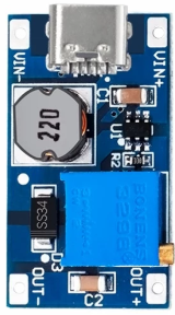
A step-down converter, also known as a buck converter, is a DC-DC converter that steps down voltage while stepping up current. Manufactured by "A" with the part ID "A," this component efficiently converts a higher input voltage to a lower output voltage. It is widely used in applications requiring lower voltage levels from a higher voltage source.
Explore Projects Built with stepdown type c


Explore Projects Built with stepdown type c
Common Applications and Use Cases
- Powering low-voltage devices (e.g., microcontrollers, sensors) from higher voltage sources
- Battery-powered systems to regulate voltage levels
- USB Type-C power delivery systems
- LED drivers and portable electronics
- Industrial and automotive applications
Technical Specifications
Key Technical Details
- Input Voltage Range: 5V to 24V DC
- Output Voltage Range: 1.2V to 12V DC (adjustable via potentiometer)
- Maximum Output Current: 3A
- Efficiency: Up to 95% (depending on input/output voltage and load)
- Switching Frequency: 150 kHz
- Operating Temperature: -40°C to 85°C
- Dimensions: 22mm x 17mm x 4mm
Pin Configuration and Descriptions
The Stepdown Type C module typically has the following pin configuration:
| Pin Name | Description |
|---|---|
| VIN | Positive input voltage terminal (connect to the higher voltage source). |
| GND | Ground terminal (common ground for input and output). |
| VOUT | Positive output voltage terminal (connect to the load). |
| ADJ | Adjustment pin (used to set the output voltage via an onboard potentiometer). |
Usage Instructions
How to Use the Component in a Circuit
- Connect the Input Voltage:
- Connect the VIN pin to the positive terminal of the input voltage source (e.g., a 12V DC power supply).
- Connect the GND pin to the ground of the input voltage source.
- Set the Output Voltage:
- Use the onboard potentiometer to adjust the output voltage. Turn the potentiometer clockwise to increase the output voltage and counterclockwise to decrease it.
- Measure the output voltage across the VOUT and GND pins using a multimeter to ensure it matches your desired value.
- Connect the Load:
- Connect the VOUT pin to the positive terminal of your load (e.g., a microcontroller or LED).
- Connect the GND pin to the ground of your load.
- Power On:
- Turn on the input power supply. The module will step down the input voltage to the desired output voltage.
Important Considerations and Best Practices
- Input Voltage: Ensure the input voltage is within the specified range (5V to 24V DC). Exceeding this range may damage the module.
- Output Current: Do not exceed the maximum output current of 3A. Use a heatsink or active cooling if operating near the maximum current for extended periods.
- Voltage Adjustment: Always measure the output voltage with a multimeter after adjusting the potentiometer to avoid overvoltage to your load.
- Polarity: Double-check the polarity of your connections. Reversing the input or output connections can damage the module.
- Filtering: For sensitive applications, consider adding input and output capacitors to reduce noise and improve stability.
Example: Using with an Arduino UNO
The Stepdown Type C module can be used to power an Arduino UNO from a 12V DC source. Here's how to connect it:
- Connect the VIN pin of the module to the 12V DC power supply.
- Connect the GND pin of the module to the ground of the power supply.
- Adjust the output voltage to 5V using the potentiometer.
- Connect the VOUT pin of the module to the 5V pin of the Arduino UNO.
- Connect the GND pin of the module to the GND pin of the Arduino UNO.
Here is an example Arduino code to blink an LED, powered by the Stepdown Type C module:
// This code blinks an LED connected to pin 13 of the Arduino UNO.
// Ensure the Arduino is powered by the Stepdown Type C module set to 5V.

void setup() {
  pinMode(13, OUTPUT); // Set pin 13 as an output pin
}

void loop() {
  digitalWrite(13, HIGH); // Turn the LED on
  delay(1000);            // Wait for 1 second
  digitalWrite(13, LOW);  // Turn the LED off
  delay(1000);            // Wait for 1 second
}
Troubleshooting and FAQs
Common Issues and Solutions
| Issue | Possible Cause | Solution |
|---|---|---|
| No output voltage | Incorrect wiring or loose connections | Double-check all connections and ensure proper polarity. |
| Output voltage is unstable | Insufficient input voltage or noisy power source | Use a stable power supply and add input/output capacitors for filtering. |
| Output voltage does not match adjustment | Potentiometer not properly adjusted or damaged | Re-adjust the potentiometer and measure the output voltage with a multimeter. |
| Module overheats | Exceeding maximum current or poor ventilation | Reduce the load current or add a heatsink/active cooling. |
FAQs
Can I use this module with a USB Type-C power source?
- Yes, as long as the input voltage is within the 5V to 24V range.
What happens if I exceed the maximum input voltage?
- Exceeding the input voltage range may permanently damage the module.
Can I use this module to charge batteries?
- Yes, but ensure the output voltage and current are suitable for the battery type and follow proper charging guidelines.
Is the output voltage regulated?
- Yes, the module provides a stable output voltage as long as the input voltage and load are within the specified range.
Can I use this module for audio applications?
- Yes, but consider adding additional filtering capacitors to minimize noise.