How to Use Blue Led Touchpad: Examples, Pinouts, and Specs
Introduction
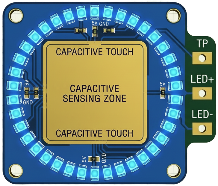
The Blue LED Touchpad is a touch-sensitive interface that combines capacitive touch sensing with a built-in blue LED for visual feedback. This component allows users to interact with electronic devices through touch gestures, making it ideal for applications requiring intuitive and responsive user interfaces. The blue LED provides immediate visual confirmation of touch events, enhancing the user experience.
Explore Projects Built with Blue Led Touchpad

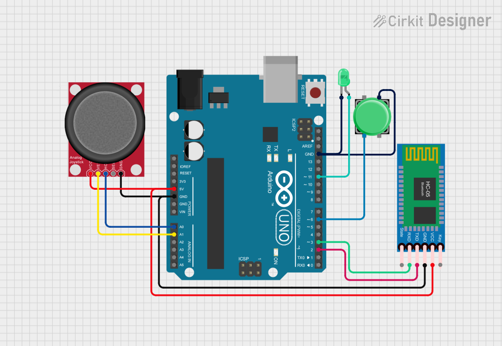
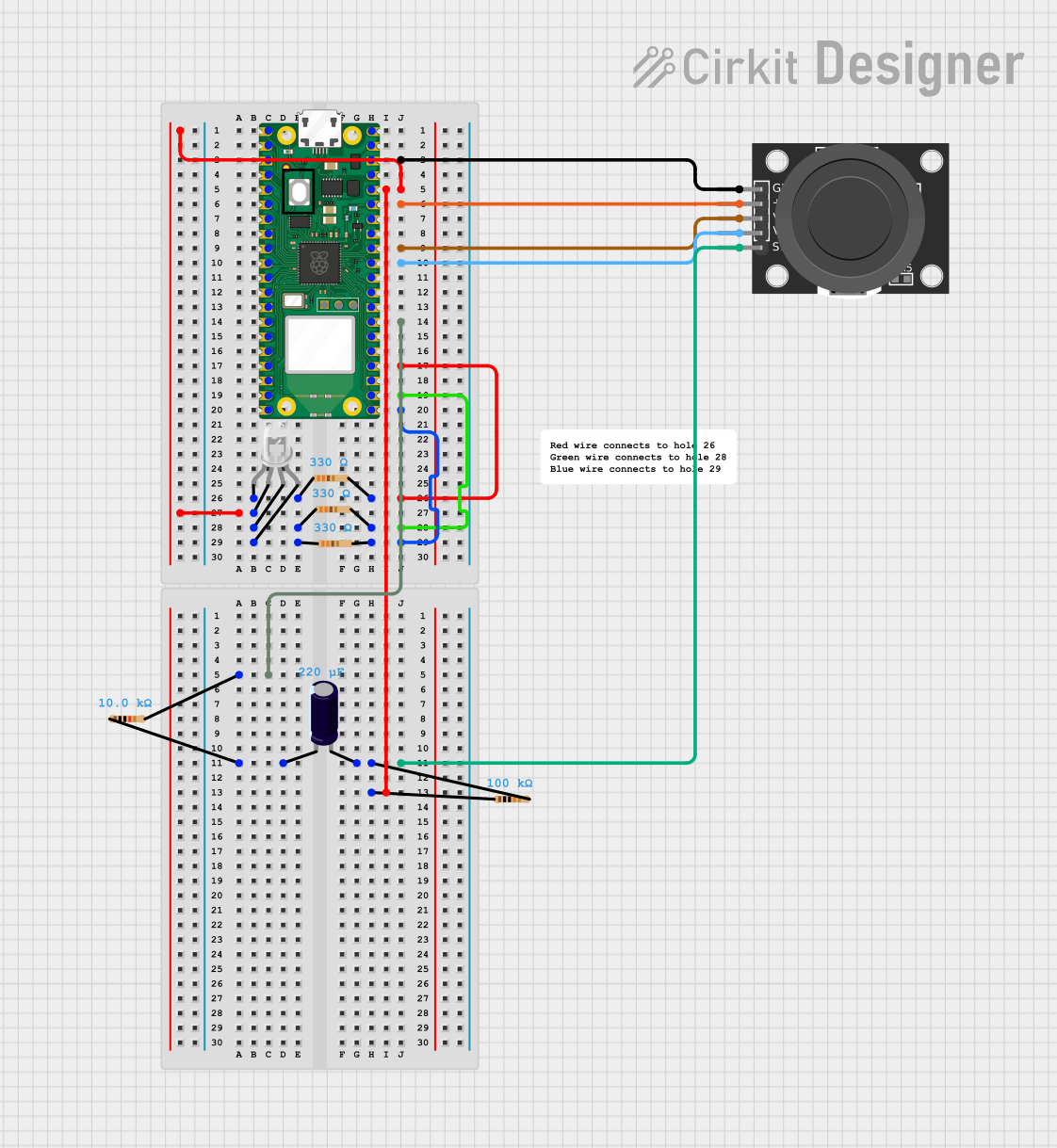
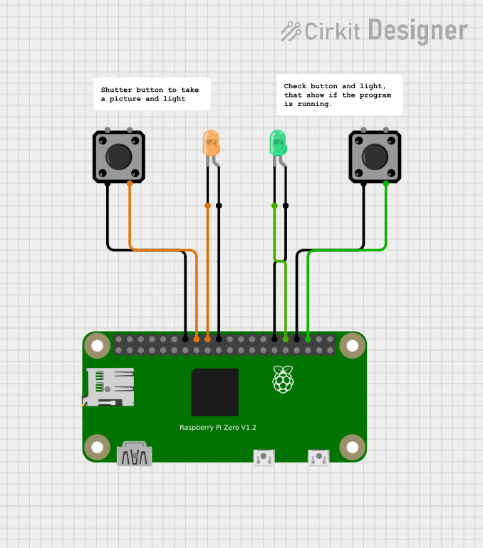
Explore Projects Built with Blue Led Touchpad
Common Applications and Use Cases
- Touch-based control panels for home automation systems
- Interactive displays and kiosks
- Wearable devices with touch-sensitive controls
- Educational and DIY electronics projects
- Prototyping touch-based user interfaces
Technical Specifications
The Blue LED Touchpad is designed for low-power, high-sensitivity applications. Below are its key technical details:
General Specifications
| Parameter | Value |
|---|---|
| Operating Voltage | 3.3V to 5V |
| Operating Current | 10mA (typical) |
| Touchpad Dimensions | 30mm x 30mm |
| LED Color | Blue |
| Touch Sensitivity | Adjustable (via external circuit) |
| Response Time | < 50ms |
| Interface Type | Digital Output |
Pin Configuration and Descriptions
| Pin Number | Pin Name | Description |
|---|---|---|
| 1 | VCC | Power supply input (3.3V to 5V). Connect to the positive terminal of the power source. |
| 2 | GND | Ground. Connect to the ground of the power source. |
| 3 | TOUCH_OUT | Digital output pin. Outputs HIGH when the touchpad is pressed. |
| 4 | LED_CTRL | LED control pin. Can be connected to a microcontroller or left floating for default behavior. |
Usage Instructions
How to Use the Component in a Circuit
- Power the Touchpad: Connect the
VCCpin to a 3.3V or 5V power source and theGNDpin to ground. - Read Touch Events: Connect the
TOUCH_OUTpin to a digital input pin on your microcontroller. The pin outputs a HIGH signal when the touchpad is pressed. - Control the LED: Optionally, connect the
LED_CTRLpin to a microcontroller pin to control the blue LED manually. If left unconnected, the LED will light up automatically when the touchpad is pressed.
Important Considerations and Best Practices
- Debouncing: Implement software debouncing in your microcontroller code to avoid false triggers caused by noise or rapid touch events.
- Power Supply: Ensure a stable power supply to avoid erratic behavior of the touchpad and LED.
- Sensitivity Adjustment: If the touchpad is too sensitive or not sensitive enough, adjust the external circuit (e.g., by changing the value of a pull-up or pull-down resistor, if applicable).
- Environmental Factors: Avoid using the touchpad in environments with excessive moisture or dust, as these can affect touch sensitivity.
Example Code for Arduino UNO
Below is an example of how to use the Blue LED Touchpad with an Arduino UNO:
// Define pin connections
const int touchPin = 2;  // Pin connected to TOUCH_OUT
const int ledPin = 13;   // Built-in LED on Arduino for visual feedback

void setup() {
  pinMode(touchPin, INPUT);  // Set touchPin as input
  pinMode(ledPin, OUTPUT);   // Set ledPin as output
  Serial.begin(9600);        // Initialize serial communication
}

void loop() {
  int touchState = digitalRead(touchPin);  // Read the state of the touchpad

  if (touchState == HIGH) {
    // If touch is detected, turn on the LED and print a message
    digitalWrite(ledPin, HIGH);
    Serial.println("Touch detected!");
  } else {
    // If no touch is detected, turn off the LED
    digitalWrite(ledPin, LOW);
  }

  delay(50);  // Small delay for stability
}
Troubleshooting and FAQs
Common Issues and Solutions
Touchpad Not Responding
- Cause: Incorrect wiring or insufficient power supply.
- Solution: Double-check all connections and ensure the power supply is within the specified range (3.3V to 5V).
False Touch Events
- Cause: Electrical noise or lack of debouncing in the code.
- Solution: Implement software debouncing and ensure proper grounding in your circuit.
LED Not Lighting Up
- Cause:
LED_CTRLpin not connected or damaged LED. - Solution: Verify the
LED_CTRLpin connection. If the pin is floating, the LED should light up automatically when the touchpad is pressed.
- Cause:
Touchpad Too Sensitive or Not Sensitive Enough
- Cause: Environmental factors or incorrect sensitivity settings.
- Solution: Adjust the external circuit (e.g., resistor values) or move the touchpad to a cleaner environment.
FAQs
Q: Can I use the Blue LED Touchpad with a 3.3V microcontroller?
A: Yes, the touchpad is compatible with both 3.3V and 5V systems.
Q: Is the touchpad waterproof?
A: No, the touchpad is not waterproof. Avoid using it in wet or humid environments.
Q: Can I disable the LED?
A: Yes, you can control the LED manually via the LED_CTRL pin or leave it unconnected to use the default behavior.
Q: How do I increase the touch sensitivity?
A: You can increase the sensitivity by adjusting the external circuit, such as reducing the value of a pull-up resistor (if applicable).