
How to Use Adafruit MOSFET Driver: Examples, Pinouts, and Specs
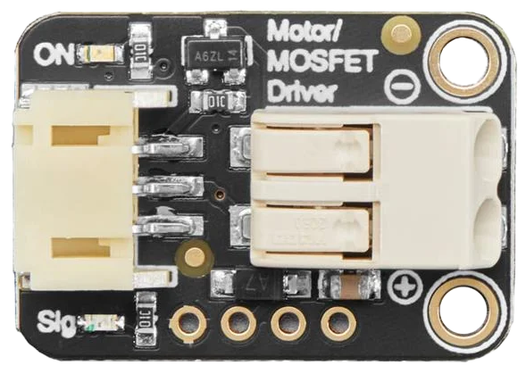
 Design with Adafruit MOSFET Driver in Cirkit Designer
Introduction
The Adafruit MOSFET Driver is a specialized circuit designed to control MOSFETs (Metal-Oxide-Semiconductor Field-Effect Transistors) efficiently. It enables high-speed switching and improved power management in electronic circuits. This driver is particularly useful in applications requiring precise control of high-power loads, such as motor drivers, LED lighting systems, and power converters. By providing the necessary gate drive voltage and current, the Adafruit MOSFET Driver ensures optimal MOSFET performance and minimizes switching losses.
Explore Projects Built with Adafruit MOSFET Driver
 Open Project in Cirkit Designer
 Open Project in Cirkit Designer
 Open Project in Cirkit Designer
 Open Project in Cirkit Designer
Explore Projects Built with Adafruit MOSFET Driver
Open Project in Cirkit DesignerOpen Project in Cirkit DesignerOpen Project in Cirkit DesignerOpen Project in Cirkit DesignerCommon Applications
- Motor control in robotics and industrial systems
- High-power LED lighting systems
- DC-DC converters and power supplies
- Pulse-width modulation (PWM) control for heating elements
- Battery management systems
Technical Specifications
The Adafruit MOSFET Driver is designed to interface seamlessly with microcontrollers and other logic-level devices. Below are its key technical details:
Key Specifications
| Parameter | Value |
|---|---|
| Input Voltage Range | 3.3V to 20V |
| Output Gate Drive Voltage | Up to 20V |
| Peak Output Current | 2A |
| Switching Frequency | Up to 1 MHz |
| Operating Temperature | -40°C to +125°C |
| Logic Input Threshold | Compatible with 3.3V and 5V logic |
Pin Configuration
The Adafruit MOSFET Driver typically comes with a simple pinout for easy integration. Below is the pin configuration:
| Pin Name | Description |
|---|---|
| VIN | Input voltage for powering the driver (3.3V to 20V). |
| GND | Ground connection. |
| IN | Logic-level input signal to control the MOSFET gate. |
| OUT | Output signal connected to the MOSFET gate. |
| EN (Enable) | Optional enable pin to turn the driver on or off (active high). |
Usage Instructions
How to Use the Adafruit MOSFET Driver in a Circuit
- Power the Driver: Connect the VIN pin to a power source within the specified voltage range (3.3V to 20V). Connect the GND pin to the ground of your circuit.
- Connect the Logic Input: Attach the IN pin to the output of your microcontroller or logic circuit. Ensure the logic level is compatible (3.3V or 5V).
- Connect the MOSFET: Connect the OUT pin to the gate of the MOSFET you wish to control. Ensure the MOSFET's source and drain are connected appropriately for your application.
- Enable the Driver: If the driver has an EN pin, connect it to a logic HIGH signal to enable the driver. If unused, tie it to VIN or leave it floating (depending on the datasheet recommendation).
- Test the Circuit: Apply a PWM or digital signal to the IN pin to control the MOSFET's switching behavior.
Important Considerations
- Gate Capacitance: Ensure the driver can handle the gate capacitance of your MOSFET. High gate capacitance may require slower switching speeds.
- Power Dissipation: Monitor the driver's temperature during operation, especially at high frequencies or with large MOSFETs.
- Decoupling Capacitor: Place a decoupling capacitor (e.g., 0.1 µF) close to the VIN pin to reduce noise and ensure stable operation.
- Logic Level Compatibility: Verify that the logic level of your microcontroller matches the input threshold of the driver.
Example: Using with Arduino UNO
Below is an example of how to use the Adafruit MOSFET Driver with an Arduino UNO to control a high-power LED:
Circuit Connections
- Connect the VIN pin of the driver to the Arduino's 5V pin.
- Connect the GND pin of the driver to the Arduino's GND.
- Connect the IN pin of the driver to Arduino digital pin 9.
- Connect the OUT pin of the driver to the gate of the MOSFET.
- Connect the MOSFET's source to GND and its drain to one terminal of the LED. Connect the other terminal of the LED to the positive power supply.
Arduino Code
// Example code to control a high-power LED using Adafruit MOSFET Driver
// and Arduino UNO. The LED brightness is controlled using PWM.

const int mosfetDriverPin = 9; // Pin connected to the IN pin of the driver

void setup() {
  pinMode(mosfetDriverPin, OUTPUT); // Set the pin as an output
}

void loop() {
  // Gradually increase brightness
  for (int brightness = 0; brightness <= 255; brightness++) {
    analogWrite(mosfetDriverPin, brightness); // Write PWM signal
    delay(10); // Small delay for smooth transition
  }

  // Gradually decrease brightness
  for (int brightness = 255; brightness >= 0; brightness--) {
    analogWrite(mosfetDriverPin, brightness); // Write PWM signal
    delay(10); // Small delay for smooth transition
  }
}
Troubleshooting and FAQs
Common Issues and Solutions
Driver Not Switching the MOSFET
- Cause: Incorrect logic level or insufficient input voltage.
- Solution: Verify that the IN pin is receiving a valid logic signal (3.3V or 5V). Check the VIN voltage.
MOSFET Overheating
- Cause: Improper MOSFET selection or insufficient gate drive voltage.
- Solution: Ensure the MOSFET is rated for the load current and voltage. Verify that the driver provides adequate gate drive voltage.
No Output Signal
- Cause: EN pin not enabled or loose connections.
- Solution: Check the EN pin state and ensure all connections are secure.
High Noise or Instability
- Cause: Lack of decoupling capacitor or poor PCB layout.
- Solution: Add a decoupling capacitor near the VIN pin and ensure proper grounding.
FAQs
Q: Can I use the Adafruit MOSFET Driver with a 24V power supply?
A: No, the maximum input voltage for the driver is 20V. Exceeding this limit may damage the component.
Q: What type of MOSFETs can I use with this driver?
A: The driver is compatible with both N-channel and P-channel MOSFETs, but ensure the gate drive voltage matches the MOSFET's requirements.
Q: Can I control multiple MOSFETs with one driver?
A: It is not recommended to drive multiple MOSFETs directly from one driver output due to increased gate capacitance. Use separate drivers for each MOSFET.
Q: Is the driver compatible with 1.8V logic?
A: No, the driver is designed for 3.3V and 5V logic levels. Use a level shifter if needed.