How to Use DC-DC Buck XL4015 5A: Examples, Pinouts, and Specs
Introduction
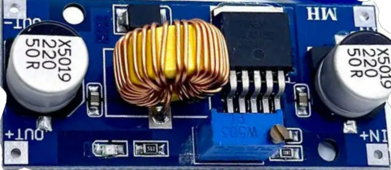
The DC-DC Buck XL4015 5A is a high-performance step-down voltage regulator designed to convert a higher DC input voltage to a lower DC output voltage efficiently. With a maximum output current of 5A, this module is ideal for powering a wide range of electronic devices, including microcontrollers, sensors, and other low-voltage components. Its compact design and adjustable output voltage make it a versatile choice for hobbyists and professionals alike.
Explore Projects Built with DC-DC Buck XL4015 5A


Explore Projects Built with DC-DC Buck XL4015 5A
Common Applications and Use Cases
- Powering microcontrollers (e.g., Arduino, Raspberry Pi) from higher voltage sources.
- Battery-powered systems requiring regulated voltage.
- LED drivers and lighting systems.
- DIY electronics projects and prototyping.
- Industrial automation and control systems.
Technical Specifications
The following table outlines the key technical details of the DC-DC Buck XL4015 5A:
| Parameter | Value |
|---|---|
| Input Voltage Range | 4V to 38V DC |
| Output Voltage Range | 1.25V to 36V DC (adjustable) |
| Maximum Output Current | 5A (with proper heat dissipation) |
| Output Power | Up to 75W |
| Efficiency | Up to 96% (depending on input/output voltage) |
| Switching Frequency | 180 kHz |
| Operating Temperature | -40°C to +85°C |
| Dimensions | 51mm x 26mm x 14mm |
Pin Configuration and Descriptions
The DC-DC Buck XL4015 5A module has the following pin configuration:
| Pin Name | Description |
|---|---|
| VIN+ | Positive input voltage terminal (connect to the higher DC voltage source). |
| VIN- | Negative input voltage terminal (connect to the ground of the DC voltage source). |
| VOUT+ | Positive output voltage terminal (connect to the load's positive terminal). |
| VOUT- | Negative output voltage terminal (connect to the load's ground terminal). |
Usage Instructions
How to Use the Component in a Circuit
Connect the Input Voltage:
- Connect the positive terminal of your DC power source to the
VIN+pin. - Connect the ground terminal of your DC power source to the
VIN-pin. - Ensure the input voltage is within the range of 4V to 38V DC.
- Connect the positive terminal of your DC power source to the
Adjust the Output Voltage:
- Use the onboard potentiometer to adjust the output voltage.
- Turn the potentiometer clockwise to increase the output voltage and counterclockwise to decrease it.
- Use a multimeter to measure the output voltage across the
VOUT+andVOUT-pins.
Connect the Load:
- Connect the positive terminal of your load to the
VOUT+pin. - Connect the ground terminal of your load to the
VOUT-pin.
- Connect the positive terminal of your load to the
Power On:
- Turn on the input power source and verify the output voltage is as desired before connecting sensitive devices.
Important Considerations and Best Practices
- Heat Dissipation: The module can handle up to 5A of current, but proper heat dissipation (e.g., a heatsink or active cooling) is required for high-current applications.
- Input Voltage: Ensure the input voltage is at least 1.5V higher than the desired output voltage for stable operation.
- Polarity: Double-check the polarity of the input and output connections to avoid damaging the module.
- Load Testing: Gradually increase the load to ensure the module operates within its rated specifications.
Example: Using the XL4015 with an Arduino UNO
The following example demonstrates how to use the DC-DC Buck XL4015 5A to power an Arduino UNO from a 12V DC power source:
- Connect the 12V DC power source to the
VIN+andVIN-pins of the XL4015 module. - Adjust the output voltage to 5V using the potentiometer.
- Connect the
VOUT+pin to the Arduino's 5V input pin. - Connect the
VOUT-pin to the Arduino's GND pin.
Here is a simple Arduino sketch to blink an LED, powered by the XL4015 module:
// Simple LED Blink Example
// Ensure the XL4015 module is set to output 5V before connecting to the Arduino.

const int ledPin = 13; // Pin connected to the onboard LED

void setup() {
  pinMode(ledPin, OUTPUT); // Set the LED pin as an output
}

void loop() {
  digitalWrite(ledPin, HIGH); // Turn the LED on
  delay(1000);                // Wait for 1 second
  digitalWrite(ledPin, LOW);  // Turn the LED off
  delay(1000);                // Wait for 1 second
}
Troubleshooting and FAQs
Common Issues and Solutions
No Output Voltage:
- Cause: Incorrect input connections or insufficient input voltage.
- Solution: Verify the input voltage is within the specified range and check the polarity of the connections.
Output Voltage Fluctuations:
- Cause: Load exceeds the module's current rating or insufficient input voltage.
- Solution: Reduce the load or increase the input voltage to meet the module's requirements.
Overheating:
- Cause: High current draw without proper heat dissipation.
- Solution: Attach a heatsink or use active cooling to dissipate heat effectively.
Cannot Adjust Output Voltage:
- Cause: Faulty potentiometer or incorrect input voltage.
- Solution: Check the input voltage and ensure it is at least 1.5V higher than the desired output voltage. If the issue persists, inspect the potentiometer for damage.
FAQs
Q1: Can the XL4015 module be used to charge batteries?
A1: Yes, the XL4015 can be used to charge batteries, but you must ensure the output voltage and current are set according to the battery's specifications.
Q2: What is the maximum input voltage for the XL4015?
A2: The maximum input voltage is 38V DC. Exceeding this voltage may damage the module.
Q3: Can I use the XL4015 to power a Raspberry Pi?
A3: Yes, the XL4015 can be used to power a Raspberry Pi. Set the output voltage to 5V and ensure the current rating meets the Raspberry Pi's requirements.
Q4: Is the module protected against reverse polarity?
A4: No, the XL4015 does not have built-in reverse polarity protection. Always double-check your connections before powering the module.