
How to Use ac_energy_meter: Examples, Pinouts, and Specs
 Design with ac_energy_meter in Cirkit Designer
Introduction
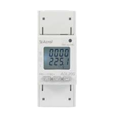
The AC Energy Meter is a device designed to measure the amount of electrical energy consumed by a circuit over time. The energy usage is typically displayed in kilowatt-hours (kWh), making it an essential tool for monitoring energy consumption and managing billing. These meters are widely used in residential, commercial, and industrial applications to track power usage and optimize energy efficiency.
Explore Projects Built with ac_energy_meter
 Open Project in Cirkit Designer
 Open Project in Cirkit Designer
 Open Project in Cirkit Designer
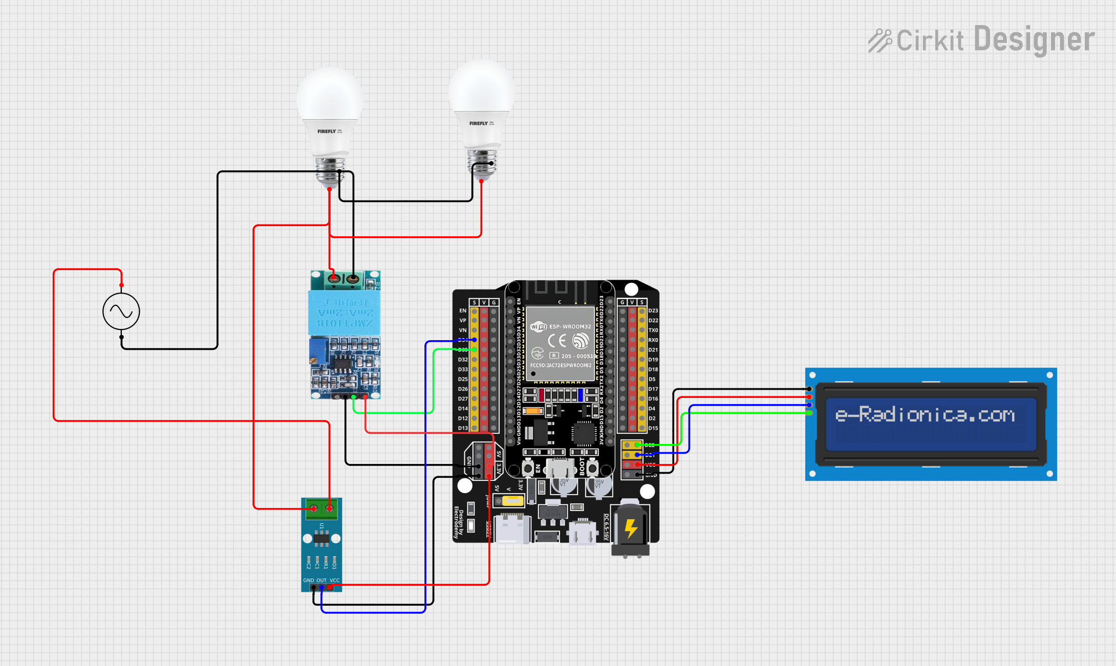 Open Project in Cirkit Designer
Explore Projects Built with ac_energy_meter
Open Project in Cirkit DesignerOpen Project in Cirkit DesignerOpen Project in Cirkit DesignerOpen Project in Cirkit DesignerCommon Applications
- Residential energy monitoring for utility billing
- Industrial energy management and load analysis
- Smart home systems for real-time energy tracking
- Renewable energy systems to measure energy production and consumption
- Research and development for power-related projects
Technical Specifications
The following table outlines the key technical details of a typical AC Energy Meter:
| Parameter | Value |
|---|---|
| Operating Voltage | 80V - 260V AC |
| Current Measurement Range | 0A - 100A (varies by model) |
| Power Measurement Range | 0W - 22kW (varies by model) |
| Energy Measurement Range | 0kWh - 9999kWh |
| Accuracy Class | ±1% |
| Frequency Range | 50Hz - 60Hz |
| Display Type | LCD/LED |
| Communication Interface | UART, RS485, or I2C (optional) |
| Power Consumption | < 1W |
| Operating Temperature | -10°C to 60°C |
Pin Configuration
The pin configuration of an AC Energy Meter depends on the specific model. Below is a general example for a meter with UART communication:
| Pin | Name | Description |
|---|---|---|
| 1 | VCC | Power supply input (e.g., 5V or 3.3V, depending on model) |
| 2 | GND | Ground connection |
| 3 | TX | UART Transmit pin for data output |
| 4 | RX | UART Receive pin for data input (if applicable) |
| 5 | AC_L | Live wire connection for AC input |
| 6 | AC_N | Neutral wire connection for AC input |
| 7 | CT+ | Current transformer positive terminal |
| 8 | CT- | Current transformer negative terminal |
Note: Always refer to the datasheet of your specific AC Energy Meter model for exact pin configurations.
Usage Instructions
How to Use the AC Energy Meter in a Circuit
- Power Supply: Connect the VCC and GND pins to a stable power source as specified in the datasheet.
- AC Input: Connect the live (AC_L) and neutral (AC_N) wires of the AC circuit to the corresponding input terminals of the meter.
- Current Transformer (CT): Attach the CT+ and CT- terminals to the current transformer. Ensure the CT is clamped around the live wire of the circuit to measure current accurately.
- Data Communication: If the meter supports UART, RS485, or I2C, connect the communication pins (e.g., TX, RX) to a microcontroller or data logger for real-time monitoring.
- Load Connection: Ensure the load is connected downstream of the meter to measure its energy consumption.
Important Considerations
- Safety First: Always disconnect power before wiring the meter to avoid electric shock.
- Calibration: Some meters may require calibration for accurate readings. Follow the manufacturer's instructions.
- CT Orientation: Ensure the current transformer is installed in the correct orientation for accurate current measurement.
- Data Logging: Use a compatible microcontroller (e.g., Arduino UNO) or software to log and analyze energy data.
- Environmental Conditions: Avoid exposing the meter to extreme temperatures, humidity, or dust.
Example: Connecting to an Arduino UNO
Below is an example of how to interface an AC Energy Meter with UART communication to an Arduino UNO for real-time energy monitoring:
#include <SoftwareSerial.h>

// Define RX and TX pins for SoftwareSerial
SoftwareSerial energyMeterSerial(10, 11); // RX = Pin 10, TX = Pin 11

void setup() {
  Serial.begin(9600); // Initialize Serial Monitor at 9600 baud
  energyMeterSerial.begin(9600); // Initialize energy meter communication

  Serial.println("AC Energy Meter Monitoring Started");
}

void loop() {
  // Check if data is available from the energy meter
  if (energyMeterSerial.available()) {
    String meterData = ""; // Variable to store incoming data

    // Read data from the energy meter
    while (energyMeterSerial.available()) {
      char c = energyMeterSerial.read();
      meterData += c;
    }

    // Display the received data on the Serial Monitor
    Serial.println("Energy Meter Data: " + meterData);
  }

  delay(1000); // Wait for 1 second before the next read
}
Note: Replace the energyMeterSerial baud rate with the correct value specified in your meter's datasheet.
Troubleshooting and FAQs
Common Issues and Solutions
No Display or Readings
- Cause: Incorrect wiring or insufficient power supply.
- Solution: Double-check all connections and ensure the power supply meets the meter's requirements.
Inaccurate Measurements
- Cause: Improper CT installation or calibration issues.
- Solution: Verify the CT orientation and perform calibration as per the manufacturer's instructions.
No Data Output via UART
- Cause: Incorrect baud rate or wiring.
- Solution: Ensure the baud rate matches the meter's specifications and check the TX/RX connections.
Overheating
- Cause: Exceeding the meter's rated current or voltage.
- Solution: Ensure the load does not exceed the meter's maximum ratings.
FAQs
Q1: Can I use the AC Energy Meter with DC circuits?
A1: No, the AC Energy Meter is designed specifically for AC circuits. For DC circuits, use a DC energy meter.
Q2: How do I reset the energy readings?
A2: Most meters have a reset button or command. Refer to the user manual for specific instructions.
Q3: Can I use multiple meters in the same system?
A3: Yes, but ensure each meter is properly isolated and configured to avoid interference.
Q4: What is the lifespan of an AC Energy Meter?
A4: The lifespan depends on the quality and usage conditions but typically ranges from 5 to 10 years.
By following this documentation, you can effectively integrate and troubleshoot an AC Energy Meter in your projects. Always consult the manufacturer's datasheet for model-specific details.