
How to Use NPN_PNP Transistor Array: Examples, Pinouts, and Specs
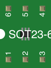
 Design with NPN_PNP Transistor Array in Cirkit Designer
Introduction
The NPN_PNP Transistor Array is a semiconductor device that integrates multiple NPN and PNP transistors into a single package. This design allows for efficient switching, amplification, and signal processing in electronic circuits. By combining complementary transistors, the array simplifies circuit design and reduces the need for discrete components, making it ideal for compact and high-performance applications.
Explore Projects Built with NPN_PNP Transistor Array
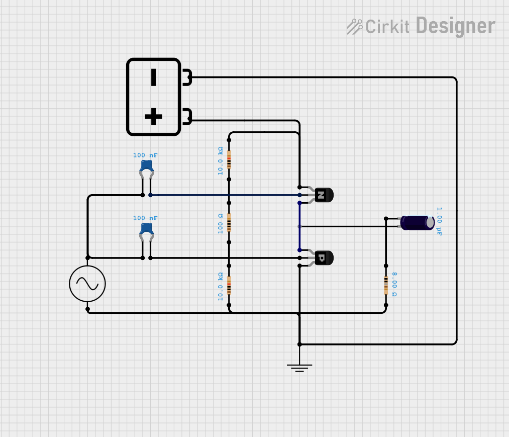 Open Project in Cirkit Designer
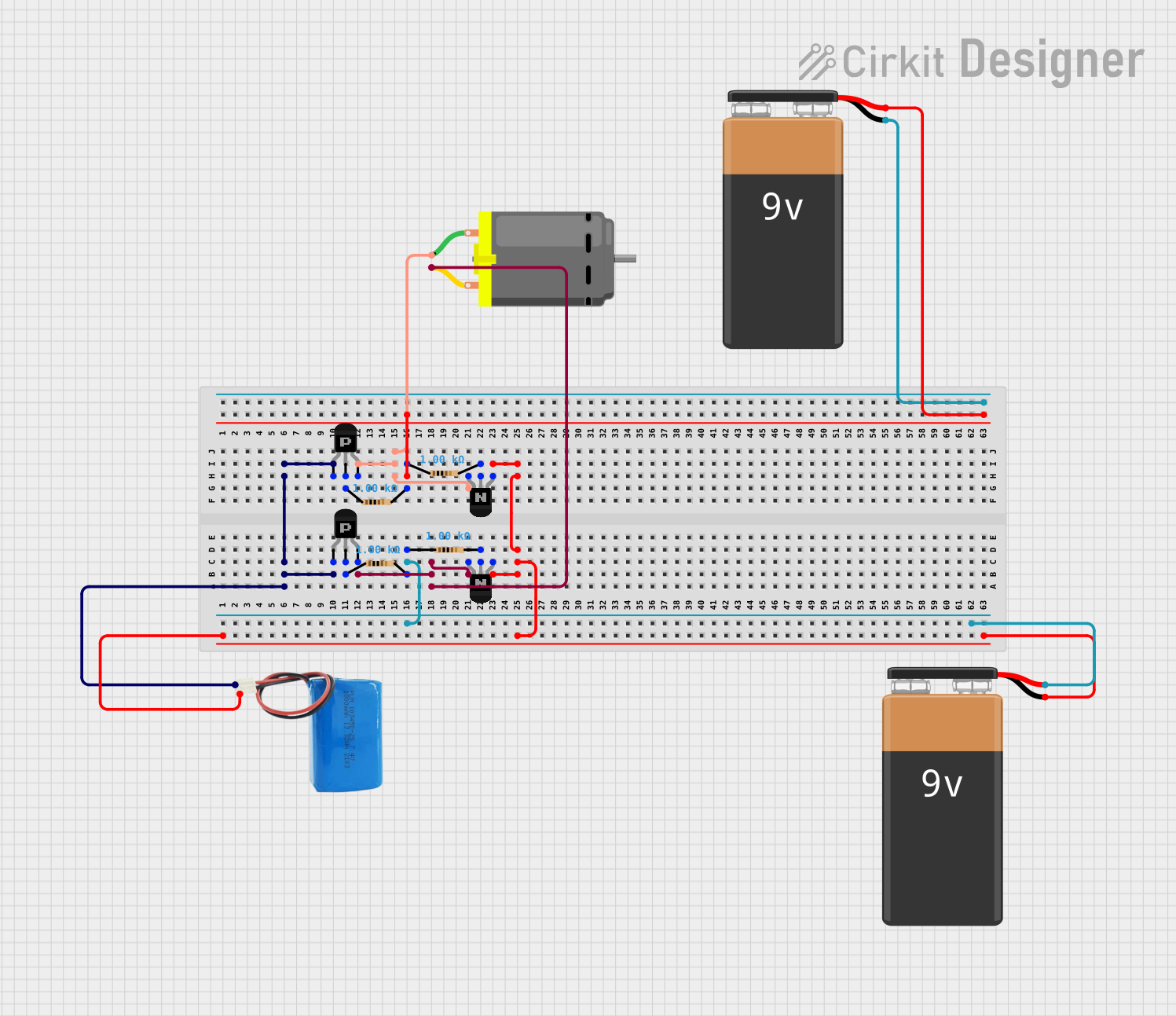 Open Project in Cirkit Designer
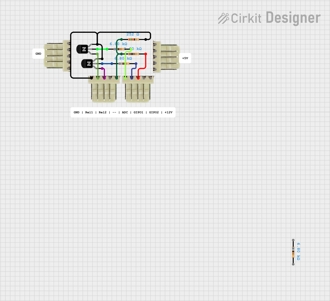 Open Project in Cirkit Designer
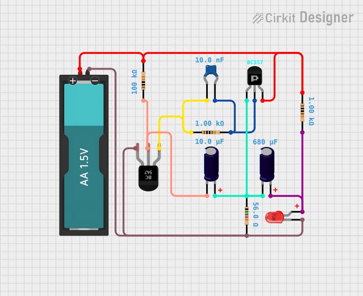 Open Project in Cirkit Designer
Explore Projects Built with NPN_PNP Transistor Array
Open Project in Cirkit DesignerOpen Project in Cirkit DesignerOpen Project in Cirkit DesignerOpen Project in Cirkit DesignerCommon Applications and Use Cases
- Motor drivers and control circuits
- Signal amplification in audio and RF systems
- Switching applications in digital and analog circuits
- LED drivers and display systems
- Logic level shifting and interfacing
- General-purpose use in compact electronic designs
Technical Specifications
Key Technical Details
- Supply Voltage (Vce): Typically up to 40V (varies by model)
- Collector Current (Ic): Up to 500mA per transistor
- Power Dissipation (Pd): Typically 1W (total package)
- Gain (hFE): 100 to 300 (varies by transistor type)
- Operating Temperature Range: -55°C to +150°C
- Package Types: DIP, SIP, or SMD (e.g., SOIC, TO-220)
Pin Configuration and Descriptions
Below is an example pinout for an 8-pin NPN_PNP Transistor Array (e.g., ULN2003 or similar):
| Pin Number | Pin Name | Description |
|---|---|---|
| 1 | IN1 | Input for the first transistor (NPN or PNP) |
| 2 | IN2 | Input for the second transistor |
| 3 | IN3 | Input for the third transistor |
| 4 | IN4 | Input for the fourth transistor |
| 5 | OUT4 | Output of the fourth transistor |
| 6 | OUT3 | Output of the third transistor |
| 7 | OUT2 | Output of the second transistor |
| 8 | OUT1 | Output of the first transistor |
Note: The exact pin configuration may vary depending on the specific model of the transistor array. Always refer to the datasheet for precise details.
Usage Instructions
How to Use the Component in a Circuit
- Power Supply: Ensure the supply voltage (Vce) does not exceed the maximum rating specified in the datasheet.
- Input Connections: Connect the input pins (IN1, IN2, etc.) to the control signals. These signals determine whether the corresponding transistor is ON or OFF.
- Output Connections: Connect the output pins (OUT1, OUT2, etc.) to the load (e.g., motor, LED, or other devices).
- Base Resistors: If required, use base resistors to limit the current into the transistor base. Some arrays include built-in resistors.
- Heat Dissipation: Ensure proper heat dissipation, especially if multiple transistors are operating at high currents.
Important Considerations and Best Practices
- Avoid Overloading: Do not exceed the maximum collector current (Ic) for any transistor in the array.
- Thermal Management: Use a heatsink or ensure adequate ventilation if the array operates at high power levels.
- Isolation: If the array includes both NPN and PNP transistors, ensure proper isolation between complementary pairs to avoid short circuits.
- Bypass Capacitors: Place decoupling capacitors near the power supply pins to reduce noise and improve stability.
Example: Using the NPN_PNP Transistor Array with Arduino UNO
Below is an example of controlling an LED array using an NPN_PNP Transistor Array and an Arduino UNO:
// Example: Controlling LEDs with an NPN_PNP Transistor Array and Arduino UNO

// Define the input pins connected to the transistor array
const int transistorPin1 = 2; // Arduino pin connected to IN1
const int transistorPin2 = 3; // Arduino pin connected to IN2

void setup() {
  // Set the transistor pins as outputs
  pinMode(transistorPin1, OUTPUT);
  pinMode(transistorPin2, OUTPUT);
}

void loop() {
  // Turn on the first LED (via transistor 1)
  digitalWrite(transistorPin1, HIGH);
  delay(1000); // Keep the LED on for 1 second

  // Turn off the first LED
  digitalWrite(transistorPin1, LOW);
  delay(500); // Wait for 0.5 seconds

  // Turn on the second LED (via transistor 2)
  digitalWrite(transistorPin2, HIGH);
  delay(1000); // Keep the LED on for 1 second

  // Turn off the second LED
  digitalWrite(transistorPin2, LOW);
  delay(500); // Wait for 0.5 seconds
}
Note: Ensure the Arduino's output pins are connected to the input pins of the transistor array through appropriate resistors if required.
Troubleshooting and FAQs
Common Issues and Solutions
Problem: Transistors are overheating.
- Solution: Check the collector current (Ic) and ensure it is within the specified limits. Use a heatsink or improve ventilation if necessary.
Problem: Output does not switch as expected.
- Solution: Verify the input signal levels. Ensure the input voltage is sufficient to turn the transistor ON.
Problem: Load is not functioning properly.
- Solution: Check the connections to the load and ensure the load's current and voltage requirements are within the transistor array's capabilities.
Problem: Noise or instability in the circuit.
- Solution: Add decoupling capacitors near the power supply pins. Ensure proper grounding and minimize long signal traces.
FAQs
Q: Can I use the NPN_PNP Transistor Array for AC signals?
A: Yes, the array can handle AC signals, but ensure the transistors are biased correctly for the application.Q: Do I need external base resistors?
A: Some transistor arrays include built-in base resistors. Check the datasheet to determine if external resistors are necessary.Q: Can I use this array to drive a motor?
A: Yes, but ensure the motor's current and voltage requirements are within the array's specifications. Use a flyback diode to protect the transistors from voltage spikes.
By following this documentation, you can effectively integrate the NPN_PNP Transistor Array into your electronic projects for reliable and efficient performance.