Cirkit Designer Logo
Cirkit Designer
Your all-in-one circuit design IDE
Home / 
Component Documentation

How to Use Mosfet P-channel: Examples, Pinouts, and Specs

Image of Mosfet P-channel
Cirkit Designer LogoDesign with Mosfet P-channel in Cirkit Designer

Introduction

A P-Channel MOSFET (Metal-Oxide-Semiconductor Field-Effect Transistor) is a type of transistor that is widely used in electronic circuits to switch or amplify electronic signals. Unlike their N-channel counterparts, P-channel MOSFETs are turned on or activated when a negative voltage is applied to the gate relative to the source terminal. They are commonly used in applications where load switching is required on the high side of the power supply, such as in power management, motor control, and battery-operated circuits.

Explore Projects Built with Mosfet P-channel

Use Cirkit Designer to design, explore, and prototype these projects online. Some projects support real-time simulation. Click "Open Project" to start designing instantly!
ESP32-Controlled Pneumatic Solenoid Valve with MOSFET Switching
Image of ESPooky32: A project utilizing Mosfet P-channel in a practical application
This circuit uses an ESP32 microcontroller to control a 12V pneumatic solenoid valve via an IRFZ44N MOSFET as a switch. The ESP32 outputs a control signal through a 220-ohm resistor to the gate of the MOSFET, which in turn controls the power to the solenoid valve from a 12V power supply. A 10k-ohm resistor provides a pull-down for the MOSFET gate to ensure it remains off when not driven by the ESP32.
Cirkit Designer LogoOpen Project in Cirkit Designer
Pixhawk-Controlled Solenoid Driver with Voltage Regulation
Image of solenoid control circuit: A project utilizing Mosfet P-channel in a practical application
This circuit uses an LM393 comparator to drive an IRFZ44N MOSFET based on the comparison between two input signals from a pixhawk 2.4.8 flight controller. The MOSFET switches a solenoid, with a diode for back EMF protection, and the system is powered by a Lipo battery with voltage regulation provided by a step-up boost converter and a step-down voltage regulator to ensure stable operation. A resistor is connected to the gate of the MOSFET for proper biasing.
Cirkit Designer LogoOpen Project in Cirkit Designer
STM32 Nucleo-Controlled Solenoid Actuation System
Image of stm32 braile: A project utilizing Mosfet P-channel in a practical application
This circuit appears to be a microcontroller-driven array of push-pull solenoids with flyback diodes for protection. The STM32 Nucleo F303RE microcontroller's GPIO pins are connected to the gates of several nMOS transistors, which act as switches to control the current flow to the solenoids. A pushbutton with a pull-up resistor is also interfaced with the microcontroller for user input, and the power supply is connected to the solenoids with ground return paths through the nMOS transistors.
Cirkit Designer LogoOpen Project in Cirkit Designer
Arduino-Controlled Solenoid Driver with pMOS Transistor
Image of Control Metal Solenoid With An Arduino UNO: A project utilizing Mosfet P-channel in a practical application
This circuit controls a solenoid using an Arduino UNO and a pMOS transistor. The Arduino toggles the solenoid on and off every second by driving the gate of the pMOS with a digital output pin through a resistor. A diode is placed across the solenoid to protect against back EMF when the solenoid is turned off.
Cirkit Designer LogoOpen Project in Cirkit Designer

Explore Projects Built with Mosfet P-channel

Use Cirkit Designer to design, explore, and prototype these projects online. Some projects support real-time simulation. Click "Open Project" to start designing instantly!
Image of ESPooky32: A project utilizing Mosfet P-channel in a practical application
ESP32-Controlled Pneumatic Solenoid Valve with MOSFET Switching
This circuit uses an ESP32 microcontroller to control a 12V pneumatic solenoid valve via an IRFZ44N MOSFET as a switch. The ESP32 outputs a control signal through a 220-ohm resistor to the gate of the MOSFET, which in turn controls the power to the solenoid valve from a 12V power supply. A 10k-ohm resistor provides a pull-down for the MOSFET gate to ensure it remains off when not driven by the ESP32.
Cirkit Designer LogoOpen Project in Cirkit Designer
Image of solenoid control circuit: A project utilizing Mosfet P-channel in a practical application
Pixhawk-Controlled Solenoid Driver with Voltage Regulation
This circuit uses an LM393 comparator to drive an IRFZ44N MOSFET based on the comparison between two input signals from a pixhawk 2.4.8 flight controller. The MOSFET switches a solenoid, with a diode for back EMF protection, and the system is powered by a Lipo battery with voltage regulation provided by a step-up boost converter and a step-down voltage regulator to ensure stable operation. A resistor is connected to the gate of the MOSFET for proper biasing.
Cirkit Designer LogoOpen Project in Cirkit Designer
Image of stm32 braile: A project utilizing Mosfet P-channel in a practical application
STM32 Nucleo-Controlled Solenoid Actuation System
This circuit appears to be a microcontroller-driven array of push-pull solenoids with flyback diodes for protection. The STM32 Nucleo F303RE microcontroller's GPIO pins are connected to the gates of several nMOS transistors, which act as switches to control the current flow to the solenoids. A pushbutton with a pull-up resistor is also interfaced with the microcontroller for user input, and the power supply is connected to the solenoids with ground return paths through the nMOS transistors.
Cirkit Designer LogoOpen Project in Cirkit Designer
Image of Control Metal Solenoid With An Arduino UNO: A project utilizing Mosfet P-channel in a practical application
Arduino-Controlled Solenoid Driver with pMOS Transistor
This circuit controls a solenoid using an Arduino UNO and a pMOS transistor. The Arduino toggles the solenoid on and off every second by driving the gate of the pMOS with a digital output pin through a resistor. A diode is placed across the solenoid to protect against back EMF when the solenoid is turned off.
Cirkit Designer LogoOpen Project in Cirkit Designer

Technical Specifications

Key Technical Details

  • Type: P-Channel MOSFET
  • Maximum Drain-Source Voltage (Vds): Specified in volts (V)
  • Maximum Gate-Source Voltage (Vgs): Specified in volts (V)
  • Maximum Continuous Drain Current (Id): Specified in amperes (A)
  • Power Dissipation (Pd): Specified in watts (W)
  • Threshold Voltage (Vth): The voltage at which the MOSFET starts to conduct, specified in volts (V)
  • Rds(on): Drain-Source On-Resistance, specified in ohms (Ω)

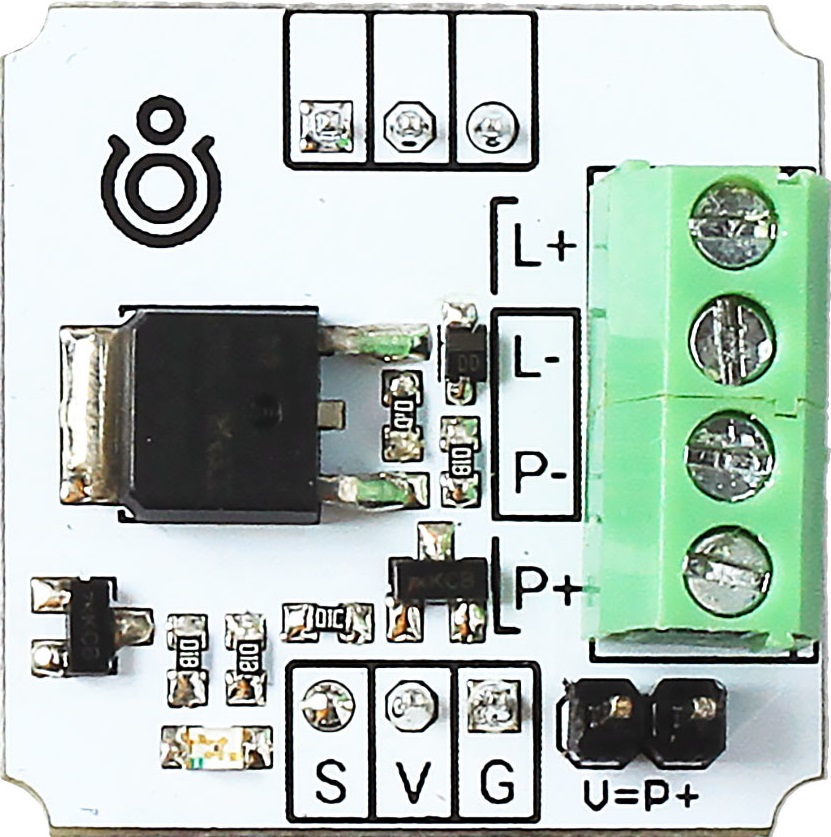
Pin Configuration and Descriptions

Pin Number Name Description
1 Gate Controls the transistor; voltage applied here regulates current flow between drain and source
2 Drain Connected to the higher potential side of the load when used in high-side switching
3 Source Connected to the power supply negative terminal; reference point for the gate voltage

Usage Instructions

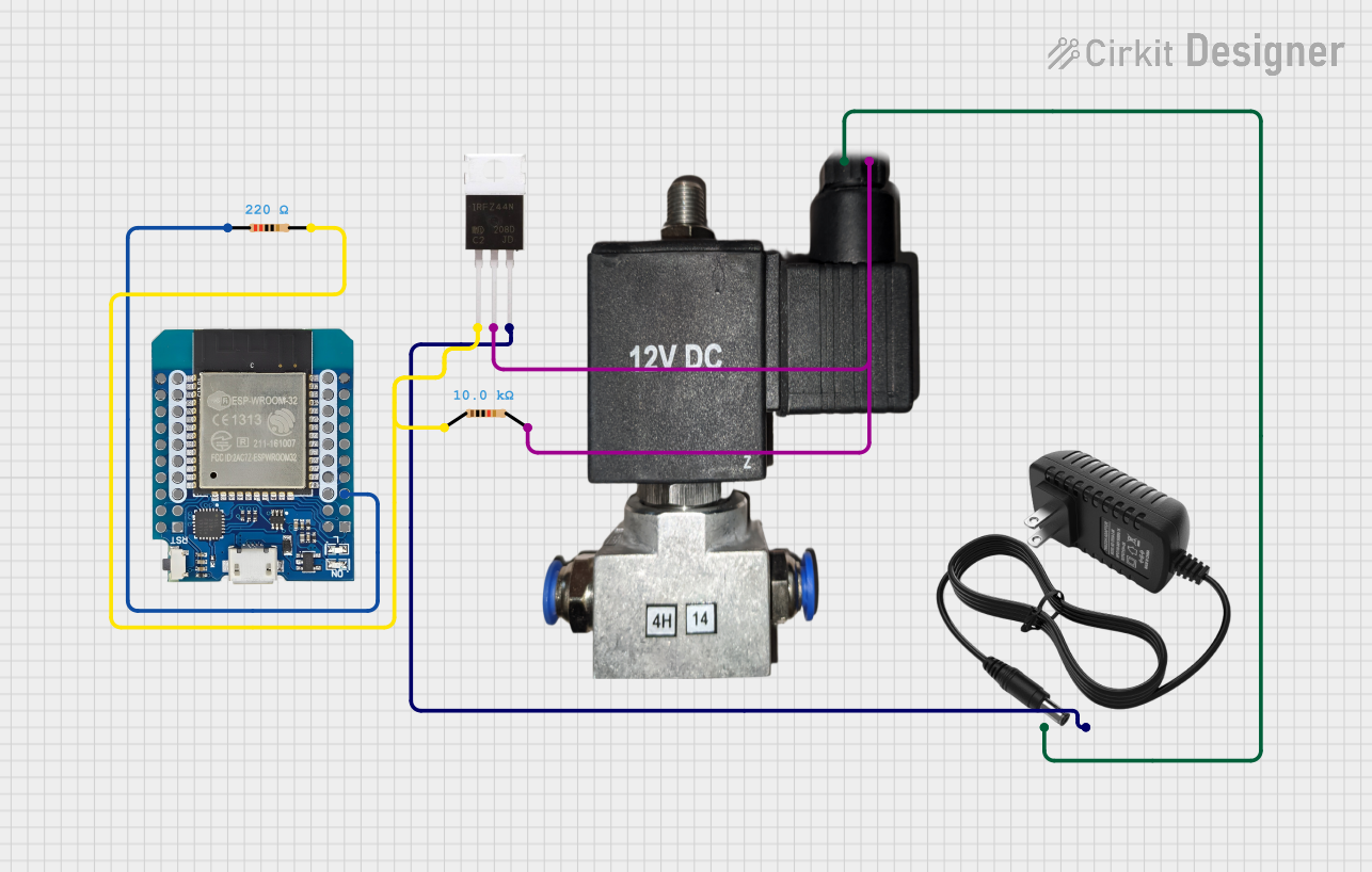
How to Use the P-Channel MOSFET in a Circuit

  1. High-Side Switching: Connect the drain to the positive side of the load, and the source to the positive terminal of the power supply.
  2. Gate Drive: Apply a negative voltage to the gate relative to the source to turn on the MOSFET. Ensure that this voltage does not exceed the maximum Vgs rating.
  3. Load Connection: Connect the load between the drain and the ground.
  4. Gate Protection: Use a gate resistor to limit the inrush current and a gate-source pull-down resistor to ensure the MOSFET remains off when there is no driving voltage.

Important Considerations and Best Practices

  • Heat Management: Ensure adequate heat sinking to manage power dissipation and prevent overheating.
  • Gate Voltage: Do not exceed the maximum gate-source voltage to avoid damaging the MOSFET.
  • Switching Frequency: Higher switching frequencies may require a driver circuit to provide sufficient gate charge and discharge.
  • ESD Sensitivity: Handle with care to prevent damage from electrostatic discharge.

Troubleshooting and FAQs

Common Issues

  • MOSFET Does Not Turn On: Check if the gate-source voltage is below the threshold voltage.
  • MOSFET Overheating: Ensure proper heat sinking and verify that the current and power ratings are not exceeded.
  • Unexpected On-State: Ensure there is a pull-down resistor on the gate to keep the MOSFET off when not driven.

Solutions and Tips

  • Gate Drive Issues: Use a gate driver if the control circuit cannot provide sufficient gate charge.
  • Heat Dissipation: Attach a heat sink to the MOSFET if it gets too hot during operation.
  • Proper Handling: Use anti-static precautions when handling the MOSFET to prevent ESD damage.

Example Code for Arduino UNO

// Example code to control a P-Channel MOSFET with an Arduino UNO

const int gatePin = 3; // Connect to the gate of the MOSFET through a resistor

void setup() {
  pinMode(gatePin, OUTPUT);
  digitalWrite(gatePin, HIGH); // Set gate high to turn off the MOSFET (default state)
}

void loop() {
  // Turn on the MOSFET by setting the gate LOW
  digitalWrite(gatePin, LOW);
  delay(1000); // Wait for 1 second
  
  // Turn off the MOSFET by setting the gate HIGH
  digitalWrite(gatePin, HIGH);
  delay(1000); // Wait for 1 second
}

Note: The code above assumes that the Arduino operates at 5V and the MOSFET gate threshold voltage is compatible. If the threshold voltage is too high, a level shifter or a different control method may be required.

This documentation provides a basic understanding of how to use a P-Channel MOSFET in electronic circuits. For specific applications and advanced configurations, refer to the datasheet of the particular MOSFET model being used.